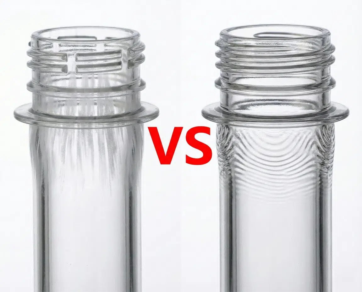
When producing PET preforms, do you often find concentric, record-like wavy lines on the neck threads? These flow marks not only ruin the aesthetics but can also lead to leakage during the blowing process, causing headaches for many injection molding managers.
Flow marks (ripples) on PET preform threads are usually caused by the "hesitation effect," where the melt cools too quickly against the mold surface, or the injection speed is insufficient to maintain the heat of the flow front. Unlike silver streaks caused by moisture, flow marks are solid, concentric ridges. You can solve this by optimizing profiled injection speeds, increasing nozzle temperature, or improving mold venting.
Many technicians panic when they see lines on a preform. Their first reaction is to increase holding pressure or check the resin dryer. This is often a waste of time and can even cause new problems like flashing. I have handled this issue in countless injection workshops, from high-speed lines to older machines. The physics behind it remains the same. It is a battle between temperature, speed, and pressure. I will guide you through the root causes one by one and show you how to troubleshoot them.
1. Identifying Flow Marks: What Do They Look Like?
Before touching any machine parameters, you must accurately identify the defect type based on appearance. The solution for "Silver Streaks" is useless for "Flow Marks."
Silver streaks are usually misty lines radiating vertically from the gate, indicating moisture in the resin. Flow marks are solid, concentric wavy rings around the preform or thread, indicating a flow or temperature issue. Distinguishing between them is the first step.
I often see a common mistake in factories. A technician sees a mark on the preform and assumes the material is not dry. He spends hours testing the dew point, changing desiccant, or stopping the machine to clean the hopper. But when he restarts, the marks are still there. This is a typical misdiagnosis.
You need to pick up a defective preform, preferably hold it up to the light, and run your fingernail over the mark.
- Silver Streaks (Splay): These look like silver spray paint. They are misty or foggy. The lines are usually vertical, spreading outward from the gate at the bottom toward the neck. This is the track of steam bubbles bursting at high heat. If you see this, go check your dryer.
- Flow Marks (Ripples): These look like ripples in a pond after you throw a stone. They are physical ridges or bumps. They are usually horizontal, circling the threads. They feel rough to the touch, but the plastic itself is transparent and solid, without fog. This is caused by "Cold Condensation."
I remember visiting a client in Southeast Asia. They were about to replace their entire dehumidifying dryer system. They were convinced the humid local air was destroying their product. I arrived, looked at the concentric waves on the threads, and told them, "Your dryer is fine. Your mold is too cold, or your injection speed is too slow." We adjusted the machine parameters, and the marks disappeared in ten minutes. Accurate diagnosis saves you unnecessary equipment investment.
To help you judge quickly, I have summarized this comparison table:
| Feature | Silver Streaks (Moisture/Splay) | Flow Marks (Ripples/Hesitation) |
|---|---|---|
| Appearance | Misty, foggy, silver lines. | Solid, transparent, wavy rings like a fingerprint. |
| Direction | Vertical (radiating from gate). | Horizontal (concentric circles around preform). |
| Tactile Feel | Usually smooth or slightly rough. | Distinct wavy, bumpy texture. |
| Root Cause | Moisture in resin, material degradation. | Melt cooling too fast, slow speed, cold mold. |
| First Action | Check resin dryer and dew point. | Check injection speed and nozzle temperature. |
2. The Physics Behind the Ripples: Melt Temperature vs. Mold Cooling
The creation of flow marks is essentially a "battle for heat" between the hot PET melt and the cold mold steel.
When molten PET touches the cold mold surface, a frozen skin forms instantly. If the subsequent injection pressure is not high enough to push this frozen skin tightly against the mold wall, or if the melt flow is too slow causing the skin to thicken, the surface wrinkles, forming flow marks.
Let us look inside the mold cavity.
On one side, you have PET melt at around 280°C. It wants to flow and fill the cavity.
On the other side, you have mold steel connected to a chiller. The water channel might be only 8°C or 10°C. The steel's job is to remove heat as fast as possible to harden the plastic.
The thread area (neck finish) is the toughest battlefield. Why?
First, the thread shape is complex, with sharp corners and thin walls.
Second, the cooling channels in the thread splits (neck rings) are designed to be very close to the cavity surface. To ensure stable neck dimensions for robot handling, we usually apply the strongest cooling here.
When plastic flows through the thread area, the moment it touches the cold mold, the outer layer freezes. We call this the "frozen layer."
If the molten plastic behind this layer is moving fast with high pressure, it can "iron out" this thin frozen layer against the mold wall, resulting in a shiny surface.
However, if the flow is slightly slow, or the mold sucks heat too fast, the frozen layer gets thick. The fresh plastic cannot push it flat. It buckles and folds over itself.
This is technically called the "Condensation Lag Effect." The melt front hesitates, cools down, viscosity spikes, and it cannot replicate the polished mold surface, leaving the gap we see as a flow mark.
Many factories run their chillers at maximum power to get the fastest Cycle Time.
"Vivian," they say, "We need a 10-second cycle!"
I understand the need for speed. But if you sacrifice appearance for speed, you lose quality. sometimes, raising the cooling water temperature for the neck splits slightly (e.g., from 8°C to 15°C) gives the plastic just 0.1 seconds longer to flow before freezing. That 0.1 second is often enough to eliminate flow marks without significantly affecting the overall cycle.
Also, the melt temperature itself is key. If your melt temperature is at the lower limit (e.g., 275°C), the PET is already viscous and resists flow. Increasing the barrel temperature by 5-10°C reduces viscosity, allowing it to flow like water into the tiny thread grooves.
3. Injection Speed: Is the "Hesitation Effect" the Culprit?
Among all dynamic parameters, injection speed has the most direct impact on flow marks. Slow speed equals giving the plastic time to freeze.
The "Hesitation Effect" occurs when the flow front slows down as it enters the thread area. If the injection speed is too low, the melt loses heat to the mold rapidly. Increasing the injection speed specifically during this phase generates shear heat to keep the material fluid, which is the most effective solution.

I want to share a story about a client in North Africa. This was a great educational experience.
They were producing 28mm PCO 1881 preforms. They were fighting a different problem: Flash (burrs) on the parting line.
To fix the flash, the operator did what most do—he lowered the injection speed.
His logic was: "If I inject slowly, the peak pressure won't be so high, the mold won't open up, and the flash will go away."
He was right; the flash disappeared.
But suddenly, every single preform had ugly waves on the threads. The customer rejected the whole batch.
The operator had unintentionally created the "Hesitation Effect."
When plastic flows through the preform body, the wall is thick and uniform, so flow is easy. But when it reaches the neck threads, the geometry becomes complex.
If the speed is low here, the flow front "hesitates." In that microsecond of pause, the cold steel grabs the heat, and the plastic freezes.
The Solution: Profiled Injection
You cannot simply use one speed from start to finish. You need "Multi-stage Injection." Modern injection machines allow you to set speed based on screw position.
Here is the strategy I usually recommend:
- Start Fast: Quickly push material into the runners and the base of the preform.
- Middle Stable: Fill the main body.
- Thread Area (Critical Point): Do not be slow here! Many people slow down here to prevent flash, but this is wrong. You must maintain enough speed to generate "shear heat" to fight the cooling.
- End of Fill: Now is the time to slow down. When the cavity is 95%-98% full (just past the threads), drop the speed rapidly to prevent impact flash, then switch to holding pressure.
The mistake my North African client made was slowing down too early. He slowed down before the threads were filled.
We adjusted the speed switchover position. We kept the speed high until the threads were full, and only dropped the speed for the final 2mm.
The result? No flash, and no flow marks.
This requires precision. You need to know exactly which screw position corresponds to the thread area. You can find this by doing a "Short Shot" test: Inject 90% weight, see where the plastic is; inject 92%, see where it is.
This is why the coordination between the injection machine and the Preform Mold, as well as the setting of process parameters, must be precise. You cannot guess; you must test scientifically.
4. Nozzle Temperature and Cold Slugs: Is the Problem Before the Mold?
Sometimes, the root cause lies before the plastic even enters the mold. A cold slug at the nozzle tip is the culprit for many "mysterious" flow marks.
If the nozzle tip temperature is too low, a small "cold slug" forms at the tip between shots. This semi-solid piece is the first thing injected into the mold. It gets pushed into the thread area and fails to melt, creating a visible mark.
This is a hardware detail often overlooked. We tend to stare at the computer screen to adjust parameters but forget to check the machine's "tail"—the nozzle.
The nozzle presses tightly against the mold's sprue bushing. The mold is cold; the nozzle is hot.
Physics dictates heat moves from hot to cold. The mold constantly steals heat from the nozzle tip.
If the contact area (Nozzle Radius) is too large, heat loss is massive. The very tip of the nozzle may drop below the melting point of PET.
A tiny plug of plastic solidifies. This is the "Cold Slug."
When the next cycle starts, the screw pushes forward. This cold slug is shot into the mold like a bullet.
Where does it go? It travels down the runner into the cavity. Because it is solid, it doesn't blend with the hot liquid plastic. It gets pushed to the side, often getting stuck in the detailed thread area.
It looks like a flow mark, but it is actually a piece of "trash" embedded in the wall.
How do we fix this?
Check Nozzle Radius:
The nozzle radius must match the sprue bushing radius perfectly. If the nozzle is too flat, the contact area is too big, and you lose too much heat. You want a line contact for a seal, not a surface contact.Check Heater Bands:
Is the heater on the nozzle actually working? Is it loose?
PET requires high heat. I often see heater bands that have slid back, leaving the nozzle tip exposed. The sensor measures the temperature further back, reading 280°C, but the tip might actually be 240°C. Move the heater band as close to the tip as possible.Increase Nozzle Temperature:
I usually set the nozzle temperature 10°C to 15°C higher than the metering zone of the barrel.
If the metering zone is 275°C, I set the nozzle to 290°C.
This compensates for the heat loss to the mold, ensuring the first drop of plastic entering the mold is 100% liquid.Valve Gate Hot Runners:
If you use a modern preform mold, you likely use a hot runner system.
If it is a "Valve Gate" (where a pin physically closes the gate), you rarely have this problem.
If it is a "Thermal Gate" (open tip), the gate tip can also freeze. You need to check the hot runner controller to ensure every tip temperature is high enough.
Hardware maintenance is fundamental. A dirty nozzle or a broken heater band renders all your process adjustments useless.
5. Mold Venting Issues: Does Air Resistance Cause Chaos?
Plastic cannot enter if air cannot exit. Trapped air creates massive back pressure, blocking smooth flow.
If the vents in the thread splits are clogged with oil or designed too shallow, the air inside the cavity gets compressed. This high-pressure air acts like a brake, slowing down the melt flow and causing premature cooling, leading to flow marks or burns.
We tend to think of the mold as empty, but it is full of air.
For plastic to fill the space, every cubic millimeter of air must be evacuated.
In the thread area, air must escape through tiny gaps between metal inserts. These are the "Vents."
If these vents are blocked, air is trapped.
As plastic rushes in, it compresses the air, spiking the pressure.
This air barrier forces the plastic to slow down (Hesitation).
As we learned: Hesitation = Cooling = Flow Marks.
Why do vents get blocked?
PET processing releases oligomers (waxy substances) and gas from additives. These condense on the mold surface and eventually fill the microscopic vent slots.
Also, machine oil seeping into the mold mixes with dust to clog vents.
My "Mystery Mark" Experience:
I had a client with a new machine, a top-tier mold, and perfect parameters.
But after 3 days of production, flow marks appeared.
They raised the temperature; it worked for 2 hours, then failed.
They increased speed; it worked for 4 hours, then failed.
They were chasing their tails.
I asked, "When was the last time you cleaned the thread splits?"
They said, "We wipe the mold every shift."
I said, "No, deep cleaning."
We removed the splits and put them in an ultrasonic cleaner. The water turned black. The vents were packed with white waxy residue.
We reinstalled the clean splits, and the flow marks vanished instantly. The process became stable.
The Solution:
- Scheduled Maintenance: Don't wait for defects. Clean regularly. Ultrasonic cleaning is the best method for thread splits.
- Check Vent Depth: For PET, vent depth is usually 0.02mm to 0.03mm. Too shallow (<0.01mm) traps air. Too deep (>0.03mm) causes flash.
- Vacuum Assist: Some high-end molds use vacuum pumps to evacuate air before injection. This fundamentally removes air resistance.
If you have tried every parameter and failed, stop the machine. Look at the mold. It is likely a venting issue, especially if the marks are always in the same spot (usually the end of the flow).
6. The Role of Gate Size: Pressure Loss is a Barrier**
The gate is the door for the plastic. If the door is too small, you lose all your energy just trying to get in.
A gate that is too small creates excessive shear and massive pressure loss. By the time the melt reaches the thread area (far from the gate), the remaining effective pressure is insufficient to pack the material, causing flow marks. Enlarging the gate can significantly reduce pressure drop.
This is a design issue, not a process one. But as a molder, you must recognize it.
Plastic enters at the base (gate) and flows up to the neck.
At the injection unit, pressure might be 100 bar.
Squeezing through a narrow gate causes pressure loss.
If the gate is tiny (e.g., 2.0mm for a large preform), the loss is huge.
Maybe only 40 bar reaches the neck.
Is 40 bar enough to push the cooling skin into the thread grooves? Probably not.
Real World Example:
I mentioned a client with a cheap second-hand mold making PCO 1810 preforms.
The problem was the gate diameter: only 2.5mm.
For their preform weight, this was too tight.
The machine was screaming, injection pressure maxed out, yet preforms had short shots and thread flow marks.
The machine was wasting energy squeezing plastic through a small hole.
We consulted the PET Bottle Mold Design Guide and calculated the shear rate.
We decided to ream the gates to 3.0mm.
It sounds small—0.5mm.
But in fluid dynamics, flow is proportional to the fourth power of the radius. Even a small increase reduces pressure drop exponentially.
The result: Smooth flow, sufficient neck pressure, no flow marks, and even a faster cycle time.
Gate Wear:
Also, check for wear. If the gate land is damaged, it disrupts flow.
If buying a new mold, ask about gate size.
If using an old mold, measure the gates. Ensure all cavities are the same size. Sometimes cavity #12 has issues because its gate is blocked or drilled smaller.
7. Practical Troubleshooting Checklist
Facing scrap, randomly pressing buttons will confuse you. You need a system.
Follow a logical order: First hardware (nozzle, vents), then process (speed, temperature). Never change multiple settings at once. Adjust one variable, observe 15 shots, then decide.
When the alarm sounds and scrap piles up, staying calm is hard. But logic is essential.
Here is the checklist I use. Print it out for your machine.
Phase 1: Easy Checks (No Stop)
- Check Material: Is it dry? (Rule out silver streaks).
- Check Melt Temp: Is actual temp matching set point? Try raising nozzle temp by 10°C.
- Check Injection Speed: Increase speed specifically at the thread filling position.
Phase 2: Process Tuning (Parameter Changes)
- Check Position: Verify where thread filling happens on the screw. Do a short shot test.
- Check Cushion: Do you have a cushion? If the screw hits 0mm every time, you have no pressure transfer. You need 5-10mm cushion.
- Mold Temp: Raise neck split cooling water temp. Try 15°C instead of 8°C.
Phase 3: Hardware Checks (Machine Stop)
- Clean Vents: Remove splits, ultrasonic clean.
- Check Nozzle Alignment: Look for leakage or cold slugs.
- Check Gate Size: Measure diameter.
Here is a priority table for daily operations:
| Priority | Action | Reason |
|---|---|---|
| 1 | Increase Injection Speed | Reduces cooling time, fights hesitation. |
| 2 | Increase Nozzle Temp | Eliminates cold slugs, lowers entry viscosity. |
| 3 | Increase Barrel Temp | Lowers overall viscosity for better flow. |
| 4 | Raise Mold Temp (Neck) | Reduces thermal shock when plastic hits steel. |
| 5 | Clean Vents | Removes air resistance for smooth filling. |
| 6 | Check Gate Size | Ensures pressure reaches the end of flow. |
Vivian's Golden Rule: Change ONE thing at a time.
If you change temperature, speed, and pressure all at once, the problem might go away, but you won't know why. Next week, when it returns, you will be guessing again. Be scientific.
Also, ensure auxiliary equipment is stable. Is your Air Compressor providing consistent pressure for valve pins? Is chiller flow steady? Unstable utilities lead to unstable quality.
8. How iBottler Ensures Precision in Every Preform Mold
The best way to prevent flow marks is starting with good mold design. We design molds to manage heat and flow perfectly.
iBottler uses advanced Moldflow simulation to optimize cooling channels and gate sizes before steel is cut. We use high-grade steel with excellent thermal conductivity and precise venting strategies to ensure your preforms are defect-free from the first trial.
At iBottler, we don't just sell metal; we sell production solutions.
We know a flow mark is not just cosmetic. It can cause leakage. If the thread surface is uneven, the cap won't seal, gas escapes, and the drink goes flat.
This is why we focus heavily on the Engineering Phase.
Before machining, we run simulations. We look at "Fill Time" and "Temperature Drop."
If the simulation shows a temperature drop in the threads, we change the design.
We might move cooling channels 1mm closer.
We might adjust the water path.
We recalculate gate dimensions.
We optimize venting.
Our Hardware Advantages:
- Optimized Hot Runners: Our manifolds maintain uniform heat. No cold spots, no cold slugs.
- Precision Venting: CNC machining cuts vents to micron tolerances—deep enough to vent, shallow enough to stop flash.
- Steel Selection: We use imported steel that polishes well and transfers heat uniformly, avoiding "hot/cold spots" that cause warping.
We also assist with integration. If you are unsure about neck design, check our Preform Neck Size Guide to reduce risks at the source. If you are worried about mold fit, see our Mounting Dimensions guide.
Choosing iBottler means choosing a partner who understands injection physics. We design problems out of the system, saving you from endless troubleshooting later.
Conclusion
The main causes of flow marks on PET preform threads are rapid melt cooling (hesitation) and insufficient pressure transfer. By distinguishing them from moisture streaks and systematically adjusting injection speed (especially at the threads), increasing nozzle temperature, and cleaning mold vents, you can eliminate this defect and ensure leak-proof, aesthetic preforms.
FAQ
Q1: Can undried material cause flow marks on threads?
No. Wet material causes Silver Streaks (Splay). These look like misty spray radiating from the gate. Flow marks are solid, wavy rings. While wet material degrades plastic and lowers viscosity (causing flash), the classic "ripple" is usually a cold flow or speed issue.
Q2: Why do flow marks always appear on the threads, not the body?
The thread area is usually the "End of Fill." It is furthest from the gate and the hardest to fill. Also, to dimensionally stabilize the neck, cooling is strongest here. Plastic is coldest and most viscous when it reaches the threads, making it prone to hesitation.
Q3: Should I increase or decrease injection speed to fix flow marks?
Generally, you should increase injection speed. High speed generates shear heat, lowering viscosity and preventing plastic from freezing as it flows over cold steel. Slow speed increases "Hesitation," making marks worse.
Q4: How deep should vents be for PET preform molds?
For thread splits, vent depth is typically 0.02mm to 0.03mm. If deeper (e.g., 0.05mm), low-viscosity PET enters the vent, causing flash. If shallower (<0.01mm), air cannot escape, causing burns and flow marks.
Q5: Can I fix flow marks just by increasing holding pressure?
Rarely. Holding pressure is for packing after the cavity is full to compensate for shrinkage. Flow marks happen during filling. If plastic freezes and wrinkles while filling, holding pressure cannot "iron it out" later. You must fix the filling phase (Speed/Temp).
Troubleshooting Summary
| Defect Cause | Key Sign | Primary Solution | Secondary Solution |
|---|---|---|---|
| Melt Hesitation | Ripples appear at slow speed. | Increase Thread Fill Speed. | Use profiled injection. |
| Cold Melt | Surface looks dull/rough. | Increase Barrel/Nozzle Temp (10-15°C). | Check heater bands. |
| Cold Mold | Bad at start-up. | Raise Neck Water Temp (e.g. 8°C -> 15°C). | Check water channels for scale. |
| Trapped Air | Marks at end of flow / burns. | Clean Mold Vents (Ultrasonic). | Check vent depth / Vacuum. |
| Cold Slug | Random solid bits embedded. | Increase Nozzle Tip Temp. | Fix nozzle/sprue contact radius. |
| Pressure Loss | Short shots + flow marks. | Enlarge Gate Size. | Check check-ring for leakage. |
