Struggling with a bottle design that looks great on screen but fails in production? The problem might be a simple 90-degree angle creating a hidden mechanical lock inside your mold.
A 90-degree bottle shoulder creates an "undercut." This is a feature that physically blocks the bottle from being ejected cleanly after the mold opens. This blockage leads to damaged products, stalled production lines, and unnecessary costs, all because of a simple, sharp corner in the design.

This might seem like a small detail, but in the world of high-speed blow molding, it's a critical flaw that can bring everything to a halt. You've spent time and money developing a unique bottle, only to find it can't be made efficiently. But don't worry, this is a common issue with a straightforward solution. Understanding the "why" behind this problem is the first step to designing better, more manufacturable bottles. Let's dive into the core mechanics of how a blow mold works and see why that sharp angle is causing you so much trouble.
Back to Basics: How a Two-Piece Blow Mold Opens and Closes?
Feeling frustrated that your bottle design is causing production issues? It often comes down to the simple physics of how the mold works. Let’s strip away the complexity and start here.
A standard blow mold consists of two halves. These halves close together to form a cavity and then open to release the bottle. They move in a simple, straight line, horizontally. Imagine opening a book; the two covers move directly away from the spine. That’s it.

Dive Deeper: The Fundamental Movement of Blow Molds
To truly grasp the challenges of bottle design, we must first respect the elegant simplicity of the machinery that creates them. Many design issues, especially those related to demolding, stem from a misunderstanding of the fundamental mechanics of a standard two-piece blow mold. The core of this mechanism is its linear, two-directional movement.
The Two Halves: A Perfect Match
At the heart of a bottle blowing machine lies the mold. Think of it as a clamshell. It's composed of two precisely machined blocks of metal, usually aluminum or steel. When these two halves are brought together, their internal cavities meet to form the exact negative space of your bottle design. A heated plastic preform is placed inside, air is blown in, and the plastic expands to take the shape of this cavity. The process is quick, efficient, and capable of producing thousands of bottles per hour. The magic is in the precision.
The two mold halves are mounted on a clamping unit. This unit’s only job is to perform two actions:
- Clamp: Push the two halves together with immense force to withstand the pressure of the blowing air.
- Unclamp: Pull the two halves apart in a perfectly straight line to release the finished bottle.
This movement occurs along a single axis. There is no tilting, no twisting, and no vertical movement in a standard setup. The line where the two mold halves meet is called the parting line. When the mold opens, the two halves retract from this parting line, creating a clear path for the bottle to be ejected.
The "Book" Analogy: A Simple Way to Visualize
I often ask clients to visualize opening a hardcover book. Place it on a table, spine up. When you open it, the front and back covers move away from each other in a simple, flat, horizontal motion. They don't lift up or slide sideways. This is exactly how a two-piece blow mold operates.
- Closed Book: The mold is clamped shut, ready for the plastic to be blown.
- Opening Book: The mold halves are retracting along a fixed, linear path.
- Fully Open Book: The mold is fully open, and the bottle is ready for ejection.
This simple, fixed trajectory is the absolute key. Any feature on your bottle that interferes with this straight-line separation will cause a problem. The mold cannot "maneuver" around a part of your bottle. It has one way to open, and the bottle must be designed to exit along that path without obstruction. This is why understanding this basic movement is not just technical trivia; it's the foundation of successful Design for Blow Molding. When we get calls about demolding issues, the first thing we review is whether the bottle design respects this fundamental, linear movement. We've seen many brilliant designs that are simply not compatible with this core mechanical constraint. And as you'll see next, this is precisely why a 90-degree shoulder turns from a design feature into a production nightmare.
| Mold Action | Mechanical Movement | Analogy | Purpose |
|---|---|---|---|
| Clamping | Two halves move linearly towards each other. | Closing a book. | To create a sealed cavity and withstand blowing pressure. |
| Blowing | Air is injected into the preform. | Inflating a balloon. | To shape the plastic against the mold walls. |
| Cooling | Chilled water circulates through the mold. | Cooling a hot pan. | To solidify the plastic bottle quickly. |
| Unclamping | Two halves move linearly away from each other. | Opening a book. | To release the finished bottle for ejection. |
Understanding this sequence and its physical limitations is crucial. We have detailed information on how to ensure your blow mold and machine are a perfect fit, which is critical for this process to run smoothly. The entire system, from the compressor to the chiller, works to support this simple, repetitive, and linear motion.
What Are Undercuts and Draft Angles? What These Terms Mean for Bottle Design?
Confused by technical jargon like "undercut" and "draft angle"? These terms might sound complex, but they represent a very simple concept that is crucial for your bottle's design and success.
An undercut is any part of your bottle's shape that hooks or grabs onto the mold, preventing a clean release. A draft angle is a tiny, intentional taper on the walls of your bottle that helps it slide out of the mold easily, preventing it from getting stuck.
Dive Deeper: The Language of Mold Making
When designers and engineers talk, it can sometimes feel like they are speaking different languages. However, two terms, "undercut" and "draft angle," are so fundamental to bottle design for manufacturability that bridging this language gap is essential. Getting these two concepts right is the difference between a product that flows off the production line and one that causes constant headaches.
Demystifying the "Undercut"
In the simplest terms, an undercut is a locking feature. Imagine trying to pull a T-shaped block straight up through a square hole. The horizontal arms of the "T" would catch on the edges of the hole, preventing it from coming out. Those arms are an undercut.
In bottle design, an undercut is any protrusion or indentation in the plastic part that is not aligned with the direction of the mold opening. Since the mold opens in a straight line, any feature that creates a "lip" or "hook" perpendicular to that opening path will get stuck.
Common examples of undercuts in product design include:
- The snap-fit clasps on a battery cover.
- The threads on a screw cap.
- A handle on the side of a crate.
In bottle design, a sharp, 90-degree angle between the shoulder and the main body is a classic, and often unintentional, undercut. The flat top of the shoulder sits directly under a corresponding flat metal surface in the mold cavity. When the mold tries to open horizontally, that metal surface physically blocks the plastic shoulder from moving with it. It's a mechanical lock.
The "Draft Angle": Your Best Friend in Mold Design
If an undercut is the villain, the draft angle is the hero. A draft angle is a small amount of taper applied to the vertical walls of a molded part. Instead of being perfectly vertical (90 degrees to the base), the walls are angled slightly inward.
Think about a stack of plastic party cups. They slide apart so easily because they have a significant draft angle; they are tapered. Now, imagine trying to separate a stack of perfectly cylindrical, straight-walled glasses. The friction and vacuum would make it incredibly difficult. That's the power of a draft angle.
In blow molding, adding a draft angle (even one as small as 0.5 to 1 degree) to surfaces parallel to the mold opening direction dramatically reduces friction. As the mold begins to open, the slight taper means the surface of the bottle immediately separates from the mold wall, creating a tiny air gap. This prevents scraping, scuffing, and sticking. The primary purpose of a draft angle is to counteract the negative effects of friction and to help the part release cleanly. It is a core principle of any good mold design guide.
The Inseparable Relationship
The relationship between these two terms is simple: You add draft angles to avoid undercuts.
| Feature | Description | Impact on Demolding | Solution |
|---|---|---|---|
| Undercut | A shape that hooks or locks into the mold. | Prevents clean release, causes part damage. | Eliminate the feature or use complex mold actions (sliders). |
| Zero Draft | A vertical wall with no taper (0° angle). | High friction, scraping, sticking. | Add a draft angle. |
| Draft Angle | A slight taper on vertical walls. | Easy, clean release with minimal friction. | Apply to all vertical faces where possible. |
A well-designed bottle incorporates generous draft angles on all vertical surfaces and ensures that no features create an undercut in the primary direction of mold pull. The 90-degree shoulder we're discussing is a perfect storm: it has zero draft on its vertical "face" (the corner itself) and it creates a massive undercut. Understanding these terms moves the conversation from "My bottle is stuck" to "I think we have an undercut issue on the shoulder; what draft angle do you recommend?" This is the kind of collaborative, informed discussion that leads to successful outcomes.
Visualizing the Problem: How a 90-Degree Shoulder Creates Mechanical Interference?
It’s hard to see the problem when looking at a 2D drawing. But in the 3D world of a mold, that sharp corner becomes a physical trap. Let's walk through how this happens.
Imagine your bottle, with its sharp 90-degree shoulder, fully formed and sitting inside the closed mold. The flat top of the shoulder is tucked directly underneath a flat metal surface of the mold cavity. When the mold starts to pull apart horizontally, that metal "roof" doesn't lift up; it slides sideways, catching the plastic shoulder and preventing it from ejecting.

Dive Deeper: From 2D Concept to 3D Reality
The leap from a beautiful 2D rendering on a computer screen to a physical, manufacturable object is where many design challenges arise. The 90-degree shoulder is a classic example of a feature that looks clean and strong in a drawing but creates a fundamental physical conflict within the confines of a blow mold. Let's break down this interference step-by-step.
Step 1: The Mold is Closed and the Bottle is Formed
Picture the moment of creation. The two halves of the blow mold are clamped shut. The hot, pliable PET plastic has been blown and is now pressed firmly against every surface of the mold cavity, faithfully replicating every detail. This includes the sharp transition at the shoulder.
- Mold Cavity: The top part of the mold cavity has a flat, horizontal surface that forms the top of your bottle's shoulder. Let's call this the "mold ceiling."
- Bottle Shoulder: Your bottle's 90-degree shoulder has a corresponding flat, horizontal surface. Let's call this the "plastic shelf."
At this moment, the "plastic shelf" is positioned directly underneath the "mold ceiling." They are perfectly parallel, separated only by the thickness of the cooled plastic.
Step 2: The Mold Begins to Open
Now, the production cycle continues. The clamp releases, and the two mold halves begin to move. As we established, they move in a single, linear direction: horizontally away from each other.
Here is the critical point of failure. The half of the mold containing the "mold ceiling" starts to slide sideways. But what about the "plastic shelf" on the bottle? It's a solid piece of plastic. It cannot compress or magically pass through the metal above it.
The "mold ceiling" attempts to slide horizontally, but the "plastic shelf" is in its direct path. This is not a gentle nudge; it's a hard stop. The plastic shoulder is physically hooked under the metal mold. This is the mechanical interference. This is the undercut in mold design in its most literal form.
Visualizing the Lock
Let's use another analogy. Imagine you are in a room with a low doorway. You can walk out easily. Now, imagine you are wearing a very wide, flat-brimmed hat. As you try to walk through the doorway, the brim of your hat (the bottle shoulder) will crash into the top of the doorframe (the mold ceiling). You are stuck. You cannot move forward. To get out, you would have to take the hat off or find a way to lift the doorframe up—neither of which is an option for a bottle inside a mold.
The table below illustrates the forces and results:
| Component | Desired Movement | Actual Result with 90° Shoulder |
|---|---|---|
| Mold Half | Slides horizontally away from the bottle. | Movement is blocked by the bottle's shoulder. |
| Bottle Shoulder | Stays stationary for vertical ejection. | Is caught and pulled sideways by the moving mold half. |
| Result | Clean separation. | Mechanical Lock. The bottle is either torn or prevents the mold from opening correctly. |
This visualization makes it clear that the problem isn't one of material stickiness or friction alone; it's a fundamental geometric conflict. No amount of mold release spray or polishing can fix a physical lock. The design itself has created a situation where the product cannot be removed from the tool that made it without damage. This is why addressing this issue at the design stage is not just a suggestion; it is an absolute necessity for successful manufacturing. And as we'll explore next, the consequences of ignoring this simple geometric fact can be costly.
The Cost of Demolding Failure: Scratched Bottles, Damaged Molds, and Production Halts?
Think a small design flaw is no big deal? The reality is that a persistent demolding issue, like one caused by an undercut, creates a cascade of expensive problems far beyond just a few bad bottles.
When a bottle gets stuck, it can be scratched or torn, instantly turning it into scrap. Worse, the constant force can wear down or chip your expensive mold. Most critically, every time the machine jams, your entire production line stops, killing your efficiency and delivery schedules.
.png.webp)
Dive Deeper: The Compounding Cost of a Single Design Flaw
In manufacturing, efficiency is everything. Profit margins are often thin, and production schedules are tight. A seemingly minor bottle design mistake, like a 90-degree shoulder, can introduce a point of failure that sends costly ripples through the entire operation. It's not just about losing one bottle; it's about the cumulative financial and operational damage that occurs over time.
Direct Material and Product Loss
The most immediate and obvious cost is the loss of the product itself. When a bottle with an undercut is forcibly ejected from a mold, several things can happen, none of them good.
- Scratches and Scuffs: The sharp edge of the mold drags across the plastic shoulder, leaving deep, unsightly scratches. The bottle is cosmetically unacceptable and must be discarded.
- Deformation: The force can warp or dent the shoulder area, compromising the bottle's structural integrity.
- Tears and Punctures: In the worst cases, the plastic shoulder can be torn away from the bottle's body, resulting in a catastrophic failure.
If a production run has a 5% scrap rate due to this single issue, that means for every 100,000 bottles produced, 5,000 are immediately thrown into the recycling bin. This is a direct loss of raw material, energy, and machine time. These failures are some of the most common issues we help clients solve, and we've compiled a guide on common PET blow molding defects and how to fix them that addresses these very problems.
Accelerated Wear and Tear on Expensive Tooling
A blow mold is a precision-engineered, expensive piece of equipment. It's designed for millions of cycles of smooth, frictionless operation. Introducing a recurring mechanical conflict puts immense stress on the tool.
Every time a plastic shoulder grinds against the mold's edge, it acts like a tiny abrasive. Over thousands of cycles, this repetitive friction will:
- Dull Sharp Edges: The crisp, precise edges of the mold cavity will become rounded and worn.
- Create Burrs: Small nicks and burrs can form on the mold surface, which then transfer to every subsequent bottle, creating even more defects.
- Cause Chipping or Cracking: In extreme cases, the force can be enough to chip the edge of the mold cavity, requiring costly and time-consuming repair. A mold that should have lasted for 3 million cycles might start failing at 1 million, tripling the long-term tooling cost for that product.
Crippling Production Downtime
Perhaps the most significant cost is the loss of production efficiency. High-speed blow molding lines are designed to run continuously. Every unplanned stop is a major problem.
- Machine Stoppages: When a bottle fails to eject, it can jam the ejection mechanism or get stuck in the mold, triggering a machine fault. An operator must then intervene, open the safety guards, manually remove the stuck bottle, and restart the line.
- Reduced Cycle Times: To mitigate the jamming, operators might be forced to slow down the entire machine, reducing the number of bottles produced per hour.
- The Ripple Effect: A halt in the blowing machine starves the downstream equipment—the fillers, cappers, labelers, and packers. The entire line sits idle, yet the overhead costs (labor, electricity, facility) continue to mount.
Let's quantify this with a conservative example:
| Cost Factor | Description | Estimated Financial Impact (per incident/hour) |
|---|---|---|
| Scrapped Bottle | Material, energy, and machine time for one bottle. | $0.05 - $0.15 |
| Downtime | Operator intervention, lost output for the entire line. | $200 - $1,000+ per hour |
| Mold Repair | Polishing, welding, and re-machining the mold cavity. | $500 - $5,000+ per repair |
When you multiply these costs over weeks and months of production, a simple design flaw transforms into a major financial liability. It proves that investing time in Design for Manufacturability (DFM) at the beginning is infinitely cheaper than dealing with the consequences of demolding issues on the factory floor.
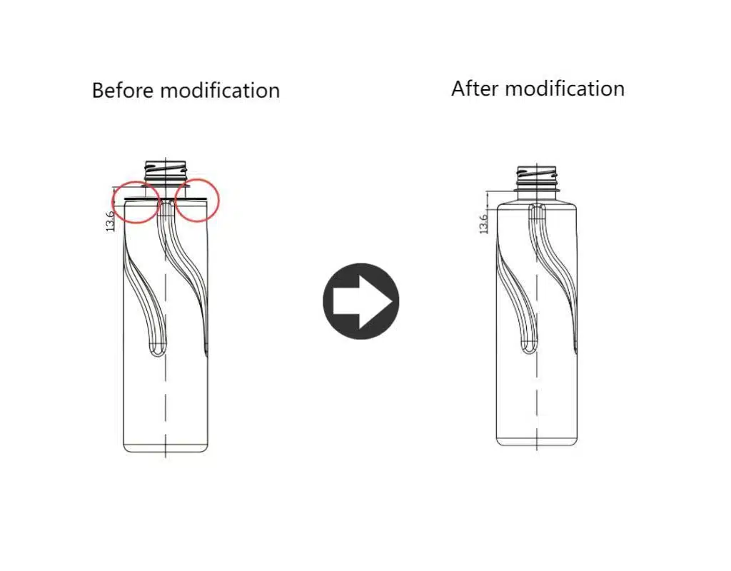
The Perfect Solution: Using a Smooth Radius to Eliminate the Undercut?
So, how do you fix this critical design flaw? The solution is surprisingly simple and elegant: you replace the sharp 90-degree corner with a smooth, curved transition, known as a radius or fillet.
This simple change completely eliminates the problem. By rounding the corner, you remove the flat "shelf" that gets caught. Instead of a mechanical lock, you create a gentle, sloping surface. This allows the bottle shoulder to slide effortlessly along the curve of the mold as it opens, ensuring a clean and damage-free release every time.
Dive Deeper: The Power of the Curve
After understanding the significant costs and frustrations caused by a 90-degree shoulder, the solution feels almost too simple. But in engineering, the most elegant solutions are often the simplest. By modifying a single geometric feature—that sharp corner—we can completely change the physics of the demolding process from a harsh mechanical lock to a smooth, gliding release.
Breaking Down the "Before" and "After"
To truly appreciate the fix, let's revisit our "before" scenario and contrast it with the "after" scenario where a radius is applied.
Before: The 90-Degree "Lock"
- Geometry: A sharp, 90-degree intersection between a vertical wall and a horizontal wall.
- Mold Interaction: This creates a "plastic shelf" sitting under a "mold ceiling."
- Demolding Action: When the mold opens horizontally, the "mold ceiling" drags across the "plastic shelf."
- Result: A hard stop. The components are locked. This is a classic undercut in mold design. The only way to separate them is by applying force, which leads to scraping, damage, and potential production halts.
After: The Smooth "Slide"
- Geometry: The sharp corner is replaced by a continuous, smooth curve (a radius).
- Mold Interaction: The mold cavity is now also a smooth curve. There is no longer a flat "mold ceiling" directly above a flat "plastic shelf."
- Demolding Action: As the mold begins to open horizontally, the bottle's curved shoulder is in contact with the mold's curved surface. The bottle is gently guided outward and away from the mold surface. The movement is now tangential to the curve.
- Result: A smooth slide. There is no mechanical interference. The bottle releases cleanly without any sticking or scraping. The mold release is seamless.
Functionality Meets Aesthetics: The "Sharp Look" Myth
A common concern I hear from brand managers and designers is that they will lose the "sharp" or "crisp" aesthetic they are trying to achieve. They envision a large, soft, rounded corner that completely changes the character of their bottle.
This is a misconception. The reality is that even a very small radius can be enough to solve the mechanical problem. A radius of just 1mm or 2mm is often sufficient to eliminate the undercut and allow for a clean release. To the naked eye, a 1.5mm radius on a bottle shoulder is barely perceptible. It maintains the visual impression of a sharp corner while completely changing the manufacturing outcome.
Here’s how different radii can be viewed:
| Radius Size | Visual Appearance | Manufacturing Performance | Typical Use Case |
|---|---|---|---|
| 0mm (90° Angle) | Perfectly sharp, visually striking. | Creates a severe undercut. Guaranteed demolding issues. | Unmanufacturable for standard two-piece molds. |
| 0.5mm - 1.0mm | Visually very sharp, almost indistinguishable from 0mm. | May be sufficient for some materials/sizes, but still risky. | Minimalist designs where every bit of sharpness counts. |
| 1.5mm - 3.0mm | Still looks crisp and well-defined. | The sweet spot. Provides excellent demolding performance. | The standard recommendation for most bottle shoulder designs. |
| > 3.0mm | Begins to look noticeably rounded. | Excellent, effortless demolding. | Designs where a softer look is desired or for very large bottles. |
This demonstrates that you can achieve a balance. You don't have to sacrifice your design intent to create a manufacturable product. The goal of good technical mold design is to find this optimal point where aesthetics and engineering function in harmony. By working with an experienced mold maker early in the process, you can define the smallest possible radius that will ensure flawless production, preserving your bottle's unique look without compromising on quality or efficiency. You can see many examples of this principle in practice in our PET bottle mold design guide.
Best Practices for Shoulder Design: Minimum Radii and Recommended Angles?
Knowing you need a radius is good, but what size should it be? For a successful design, you need specific, actionable parameters to follow.
As a general rule, the bigger the radius, the easier the release. But for a starting point, a minimum radius of 1.5mm is a widely accepted industry best practice. The ideal size depends on your bottle's material and shape, so early communication with your mold maker is key to avoiding redesigns.
Dive Deeper: Actionable Guidelines for Designers
Moving from theory to practice requires concrete numbers and guidelines. While every bottle project is unique, there are well-established best practices in bottle shoulder design that can serve as an excellent starting point for any designer. Following these guidelines will drastically reduce the risk of running into manufacturing problems down the line.
The Golden Rule: "Bigger is Better"
The fundamental principle for shoulder radii is simple: within the constraints of your aesthetic goals, a larger radius is always better for manufacturing. A larger radius provides a gentler, more forgiving slope for the bottle to slide against during ejection. This reduces friction, minimizes the chance of scuffing, and promotes a smoother, faster cycle time.
While designers might be tempted to push for the absolute smallest radius possible to achieve a "sharper" look, it's a game of diminishing returns that introduces risk. A slightly larger, safer radius will go unnoticed by the end consumer but will be greatly appreciated by the production team and will result in a higher quality final part.
Establishing a Baseline: Minimum Recommended Values
To give designers a safe place to start, the industry has developed some rules of thumb. These are not absolute laws but are based on decades of experience across countless projects.
Minimum Shoulder Radius:
For most standard PET bottles (from 250ml to 1.5L), a minimum shoulder radius of 1.5mm is highly recommended.
- Below 1.5mm: You enter a "caution zone." Radii between 1.0mm and 1.5mm might work, but they are more sensitive to material variations and mold conditions. Anything below 1.0mm is approaching a sharp corner and significantly increases the risk of demolding issues.
- 1.5mm to 3.0mm: This is the ideal "safe zone" for most designs. It provides excellent demolding characteristics while maintaining a crisp visual appearance.
- Above 3.0mm: This offers maximum manufacturability but starts to create a visibly "soft" or "rounded" look, which may or may not align with your brand's aesthetic.
Here is a table of general recommendations:
| Bottle Size / Type | Material | Minimum Recommended Radius | Optimal Radius Range | Notes |
|---|---|---|---|---|
| Small Bottles (<500ml) | PET | 1.5 mm | 1.5 - 2.5 mm | Smaller parts cool faster and are more rigid, making a good radius crucial. |
| Medium Bottles (500ml - 1.5L) | PET | 1.5 mm | 2.0 - 3.5 mm | This is the most common category; sticking to best practices is key. |
| Large Bottles (>1.5L) | PET | 2.0 mm | 3.0 - 5.0 mm | Larger surface area creates more friction; a larger radius helps overcome this. |
| Household Chemicals | HDPE | 2.0 mm | 2.5 - 4.0 mm | HDPE is softer than PET and can be more prone to scuffing if the radius is too small. |
The Crucial Role of Early Collaboration
These numbers are a starting point, not a substitute for expert advice. The optimal radius and draft angles for your specific bottle depend on a combination of factors:
- Bottle Geometry: A tall, slender bottle behaves differently from a short, wide one.
- Plastic Material: PET, HDPE, and PP have different shrinkage rates and levels of flexibility.
- Bottle Weight: A heavier, thicker preform results in a more rigid bottle that is less forgiving of sharp corners. Even choosing the right preform neck size can influence the overall rigidity.
- Mold Cooling: The efficiency of the mold cooling system (chillers are essential!) affects how the plastic solidifies and shrinks.
This is why the single most important best practice is to engage your mold manufacturer early in the design process. Don't wait until you have a finalized 3D model. Bring us, or any experienced mold engineer, into the conversation at the concept stage. We can provide immediate feedback, recommend the optimal parameters for your specific project, and help you avoid a costly and time-consuming redesign process. A quick DFM (Design for Manufacturability) review can save you weeks of delays and thousands of dollars.
Exceptions and Solutions for Square Bottles and Other Special Shapes?
But wait, you've seen square bottles on the shelf. How do they exist if sharp corners are a problem? This is a common point of confusion, but the answer lies in clever design and, sometimes, more complex tooling.
Those "square" bottles are not truly square. They have carefully calculated, often large, radii on all their corners to allow for release. For truly complex shapes with unavoidable undercuts, like integrated handles, manufacturers use advanced molds with moving parts called sliders, which are much more expensive.
Dive Deeper: The Illusion of the Sharp Corner
It’s easy to look at the variety of bottles on a supermarket shelf and question the rules. You see bottles that appear square, bottles with intricate grips, and bottles with unique branding elements that seem to defy the simple physics we've discussed. This doesn't mean the rules are wrong; it means that clever engineers have found ways to work within them or, in some cases, have employed more advanced technology to get around them.
The Secret of the "Square" Bottle
The most common "exception" people point to is the square or rectangular bottle, popular for juices, dairy products, and household chemicals. From a distance, they look like they have sharp, 90-degree corners. But if you pick one up and look closely, you'll discover their secret: they have significant corner radii.
The vertical corners (where the sides meet) and the horizontal corners (at the shoulder and base) are all rounded. Designers of these bottles are masters of perception. They use flat panels to give the impression of a square shape, but they incorporate radii that are large enough—often 5mm, 10mm, or even more—to ensure the bottle can be manufactured without undercuts. The "squareness" is an illusion created by the contrast between the flat faces and the curved corners. This is a perfect example of excellent Design for Blow Molding, where the aesthetic intent is achieved through smart, manufacturable geometry.
My Experience with Ambitious Designs: The Shamrock Bottle
This reminds me of a project with a passionate entrepreneur from Ireland. He came to us with a brilliant concept for a new beverage. His bottle design was a beautiful, stylized three-leaf shamrock. It was unique, deeply tied to his brand's identity, and looked fantastic in the renderings. However, from a manufacturing standpoint, it was a minefield of problems.
The design featured deep, sharp grooves between the "leaves" of the shamrock and, most critically, a nearly 90-degree transition at the shoulder to maintain the crisp shape. I had to have a tough but necessary conversation with him. I explained that the deep grooves would trap air and lead to incomplete forming, and the sharp shoulder would create a severe undercut in the mold design, making it impossible to eject the bottle from a standard two-piece mold.
He was initially disappointed, worried that we were trying to dilute his vision into a generic "bottle shape." Instead of just saying "no," we treated it as a collaborative challenge. We used our 3D printing and rapid prototyping service to create physical models of his original design and a few modified versions we proposed. We softened the grooves and, most importantly, replaced the 90-degree shoulder with a smooth 3mm radius. When he held the models in his hands, he saw that the modified design was still clearly a shamrock. It retained 95% of his original vision but was now 100% manufacturable. This is the partnership I love: protecting a client's creative spark while guiding it into a successful, physical product.
When Undercuts are Unavoidable: Sliders and Core Pulls
What about features where an undercut is the entire point, like the handle on a large detergent bottle or the snap-fit feature on a lid? For these special cases, a simple two-piece mold won't work. Manufacturers must use more complex and expensive tooling that incorporates moving parts.
- Sliders (or Slides): These are separate pieces of the mold that can move in a different direction (usually perpendicular) to the main mold opening. A slider can form the inside of a handle, for example. Before the main mold opens, the slider retracts, pulling itself out of the handle and clearing the undercut.
- Core Pulls: These are similar to sliders but usually refer to moving parts that form internal features.
| Tooling Type | Complexity | Cost | Cycle Time | Best For |
|---|---|---|---|---|
| Standard 2-Piece Mold | Low | $ | Fastest | Most bottles and jars without undercuts. |
| Mold with Sliders | High | $$$ | Slower | Bottles with side handles, deep indentations, or side-facing features. |
While these technologies are powerful, they come with significant downsides:
- Cost: A mold with sliders can be 50% to 200% more expensive than a standard mold due to the complex mechanisms.
- Maintenance: More moving parts mean more potential points of failure and higher maintenance requirements.
- Cycle Time: The extra movement of the sliders adds time to each production cycle, reducing overall output.
For these reasons, the first and best approach is always to try and design the undercut out of the part. Using sliders is a solution for when a feature is absolutely essential and cannot be achieved any other way. For 99% of bottle designs, a simple radius is the most efficient, reliable, and cost-effective solution.
Preventing Problems at the Source: Make Your Mold Engineer Your Creative Partner?
Worried that your creative vision will be constantly rejected by technical constraints? The key is to shift your mindset. Don't see a mold engineer as a roadblock; see them as a creative partner who helps make your vision a physical reality.
The best way to prevent costly manufacturing issues is to involve a mold expert at the very beginning of your design process. A Design for Manufacturability (DFM) review before your design is finalized can identify and solve problems like undercuts early, saving you time, money, and frustration.

Dive Deeper: A Partnership for Success
The traditional product development process can often feel like a relay race, where the designer hands off a "finished" design to the engineer, who then has to figure out how to make it. This siloed approach is the root cause of many of the problems we've discussed. It creates a dynamic of "us vs. them," where designers feel their creativity is being stifled and engineers feel they are being handed impossible tasks. A much more effective approach is a collaborative partnership that begins on day one.
The Power of a DFM Review
DFM, or Design for Manufacturability, is a formal process, but its philosophy is simple: think about how you're going to make something while you're still designing it. A DFM review is a check-up for your design, specifically focused on identifying any features that could be difficult, expensive, or impossible to manufacture effectively.
When it comes to blow molding, a DFM review performed by an experienced mold engineer will analyze:
- Undercuts and Draft Angles: The very issues we've been discussing. Are there any features that would prevent the bottle from being ejected? Are there adequate draft angles on all vertical surfaces?
- Wall Thickness: Is the plastic distribution likely to be even? Are there any areas that could become too thin and weak or too thick and heavy?
- Parting Line: Where is the best place to put the parting line (where the mold halves meet) to minimize its visual impact and ensure the mold is strong?
- Material Flow: How will the plastic stretch and flow into the fine details of the mold? Are any radii too tight or any features too deep?
- Cooling and Cycle Time: Does the design allow for efficient mold cooling? Are there any thick sections that will slow down the production cycle? We know how crucial a proper chiller connection is to a PET blow mold.
Conducting this review before the design is finalized is critical. It's infinitely easier and cheaper to change a line in a CAD file than it is to re-machine a multi-thousand-dollar steel mold.
Shifting "When" You Ask for Help
The most successful projects I've worked on are those where the client brought us in early. Instead of receiving a finished design and having to deliver bad news, we get to be part of the creative process.
The Old Way (Inefficient):
- Brand develops a concept.
- Designer creates a "final" 3D model.
- Design is sent to the mold maker for a quote.
- Mold maker identifies multiple manufacturing flaws (like a 90-degree shoulder).
- Designer has to go back and make major revisions.
- Frustration, delays, and extra costs are incurred.
The New Way (Collaborative and Efficient):
- Brand develops a concept.
- Designer creates initial sketches or a rough 3D model.
- Designer and brand consult with a mold engineer (like iBottler).
- The engineer provides feedback on manufacturability, suggesting tweaks to radii, angles, and features.
- The designer incorporates this feedback into the final, beautiful, and fully manufacturable design.
- The project moves smoothly from design to tooling to production.
At iBottler, we pride ourselves on being this kind of creative partner. We have the technical expertise and a vast library of data, including the mounting dimensions for 80% of blow molding machines worldwide, which means we can think about the entire production ecosystem from the start. We can even help you create rapid prototypes and 3D printed samples to validate the design's look, feel, and manufacturability long before any metal is cut.
By inviting an engineer to the table early, you're not sacrificing creativity. You are augmenting it with technical expertise to ensure the vision you have in your head is the exact one that ends up on the shelf.
Conclusion
A 90-degree shoulder creates a mechanical lock, or undercut, in a blow mold. The simplest, most effective solution is replacing it with a small radius for a smooth, trouble-free release.
Frequently Asked Questions (FAQ)
1. What is the absolute minimum radius I can use on a bottle shoulder?
While it depends on the bottle's size and material, a radius of 1.5mm is a safe and highly recommended starting point for most PET bottles. Going below 1.0mm is very risky and often leads to the demolding issues we've discussed. It's always best to consult your mold maker for your specific design.
2. Will adding a radius to the shoulder make my bottle look too "soft" or "round"?
This is a common concern, but in most cases, the answer is no. A 1.5mm or 2mm radius is barely perceptible to the naked eye but makes a world of difference in manufacturing. It maintains a "crisp" visual appearance while eliminating the undercut problem. You can achieve a sharp look without creating a manufacturing nightmare.
3. How can square bottles exist if 90-degree angles are a problem?
If you look closely at any "square" or rectangular bottle on the market, you will see that its corners are not truly 90 degrees. They all incorporate surprisingly large radii, often 5mm or more, on both the vertical and horizontal corners. The design uses flat panels to create the illusion of a square shape while using smart geometry to ensure it can be demolded easily.
4. My design has a handle, which is a necessary undercut. What do I do?
For essential features like handles that are by definition undercuts, a more complex and expensive type of mold is required. These molds use moving parts called "sliders" or "side-actions" that pull out of the undercut feature before the main mold opens. While this is an effective solution, it significantly increases the cost and complexity of the tooling. The first choice should always be to design out the undercut if possible.
5. When is the best time to talk to a mold engineer about my design?
As early as possible! Do not wait until your design is "finished." The most efficient and cost-effective time to consult a mold maker is at the concept or early design stage. A quick Design for Manufacturability (DFM) review can identify potential issues and provide solutions before any significant time or money has been invested, ensuring your creative vision can become a successful physical product without costly delays.
🔗 Related Pages on Our Website
Automatic Blow Molding Machines – iBottler
Discover our full range of customizable automatic PET bottle blow molding machines.Blow Bottle Mold – iBottler
Explore our precision blow molds designed for PET and PP bottles.Preform Mold – iBottler
Learn more about our high-precision preform molds suitable for various injection molding machines.PET Wide Mouth Jar Project Starter Guide: Equipment, Molds & Process Explained
Pros and Cons: Should You Choose PET Blow Moulding for Your Bottle Project?
Worried About Blow Mold Fit? We Have Mounting Dimensions for 80% of Blow Molding Machines Worldwide
Can One Semi‑Automatic Blow Molding Machine Produce All Bottle Sizes? Here’s Why Not
Why Do Krones Blow Molding Machine Users Come to Us for Their Molds?
Why Do PET Preforms Come in Different Colors? Function, Application, and Production Tips
How to Set Parameters for 600ml Bottles on a Semi-Automatic PET Blowing Machine?
From 3D Printed Samples to Production: How Can You Rapidly Validate Blow Mold Designs?
How to Choose the Right Preform Neck Size for Your PET Bottle Project