Are you constantly fighting against high Acetaldehyde (AA) levels, inconsistent intrinsic viscosity (IV) drops, or visual defects like gate stringing? Please believe me, these are not just random process errors; they are symptoms of specific component failures within your mold's anatomy. Ignoring the specific maintenance needs of your valve gate system is a fast track to rejected batches and lost contracts.
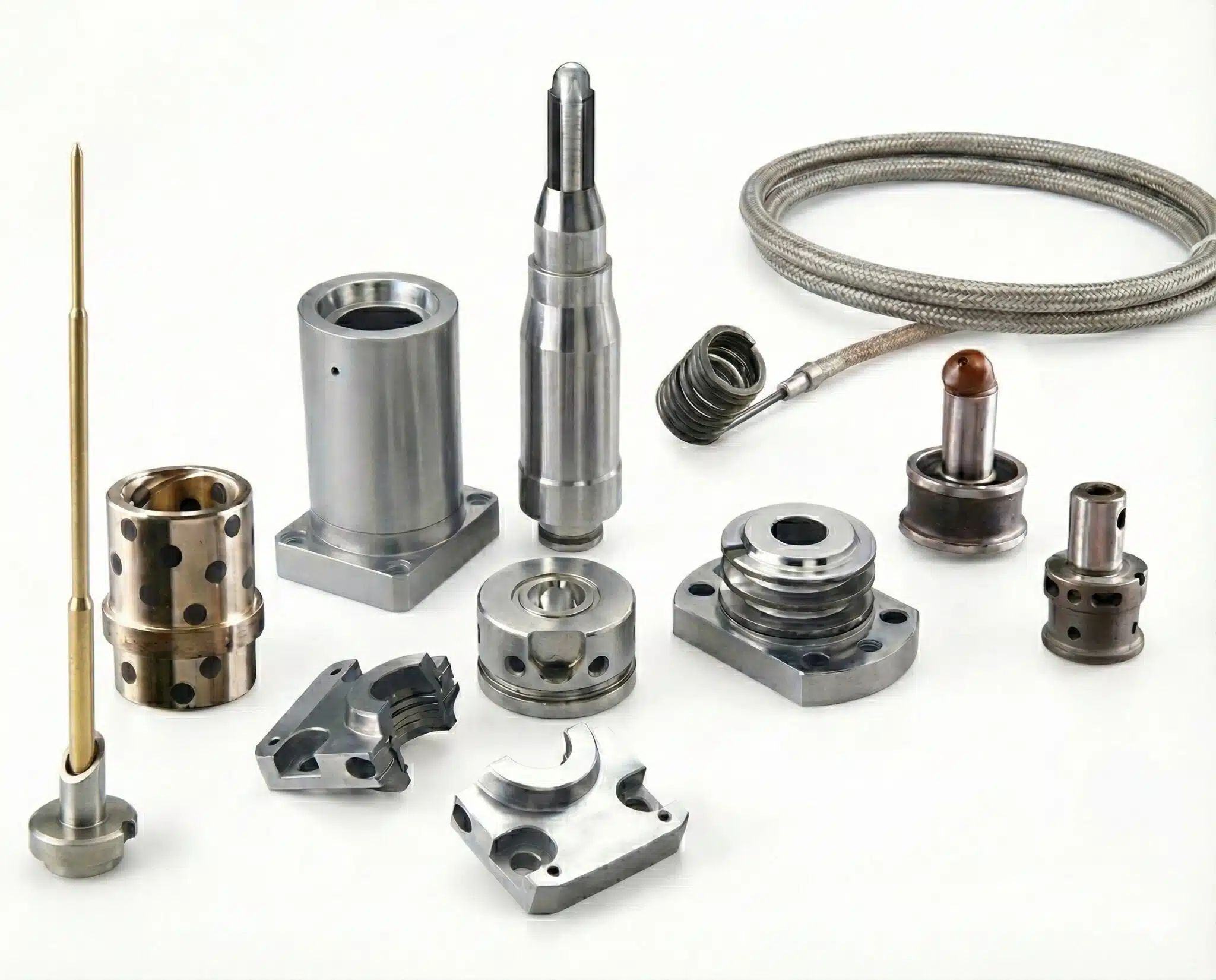
A valve gate PET preform mold is a high-precision assembly divided into the Hot Half (manifold, heaters, valve pins) and the Cold Half (core, cavity, lip cavity). Understanding the specific metallurgy, thermal dynamics, and mechanical tolerances of each component—from the pneumatic cylinder to the neck ring—is the only way to ensure tail-free injection and consistent cycle times under 15 seconds.

Many production managers treat the mold as a single "black box"—plastic goes in, preforms come out. But at iBottler, we see it as a synchronized orchestra of thousands of parts. If one O-ring fails, or one valve pin is misaligned by just 0.05mm, the entire movement stops. To truly control your quality and profitability, we must dissect this machinery piece by piece, examining the critical functions and maintenance protocols that separate a world-class operation from a mediocre one.
The Heart: Valve Pin and Pneumatic Cylinder System
Does the microscopic movement of a single steel pin really determine the structural integrity of your entire bottle production? The answer is yes, absolutely.
The valve pin and pneumatic cylinder assembly form the active gating system. The cylinder drives the pin to physically seal the gate, eliminating the "tail" on the preform. Precision here is non-negotiable; a sluggish pin causes gate crystallinity, while a misaligned pin destroys the gate insert.
The valve gate system is the defining feature that separates high-quality preform molds from older thermal gate technologies. In my years of troubleshooting at iBottler, I have found that nearly 60% of gate-related defects—such as stringing, crystallinity, and leaking—are mechanical issues originating here, not thermal issues.
The Pneumatic Cylinder is the muscle behind the operation. It is housed in the top clamp plate and actuates the pin. If your air pressure drops below 6 bar, or if the air is contaminated with moisture (causing the internal piston seals to swell or corrode), the pin closes with a delay. Even a 100-millisecond delay allows the plastic to cool and semi-solidify before the pin seats. This creates "gate crystallinity"—a brittle white spot that acts as a stress concentrator, causing the bottle to burst during the stretching phase in your bottle blowing machine.
The Valve Pin itself is arguably the most abused component in the entire mold. It must slam into the gate insert thousands of times per hour. We have largely moved away from standard H13 steel for high-cavity molds. We now recommend TZM (Titanium-Zirconium-Molybdenum) or Tungsten Carbide tips. Why? Because they conduct heat faster away from the gate and resist wear significantly better. A worn pin tip allows plastic to leak back up the stem, causing the pin to stick or seize.
Comparison of Valve Pin Materials:
| Material Type | Wear Resistance | Thermal Conductivity | Cost Efficiency | Best Application |
|---|---|---|---|---|
| Standard H13 Steel | Low | Moderate | High (Low Cost) | Low volume, prototyping, non-critical parts. |
| TiN Coated H13 | Medium (Surface only) | Moderate | Medium | Standard water preforms, budget-conscious high volume. |
| Tungsten Carbide | Very High | High | Low (High Cost) | High-speed CSD, Hot Fill, abrasive resins (RPET). |
| TZM Alloy | Extreme | Very High | Low (High Cost) | Premium optical quality, fastest cycle times (<10s). |
Maintaining this system requires a strict protocol. Every 3 million shots, you must check the concentricity of the pins. If a pin is bent by even 0.02mm, it will wear the gate insert into an oval shape, leading to flash that cannot be fixed by process adjustments.
The Shaping Unit: Core and Cavity Inserts
If the valve pin controls the flow, the core and cavity define the reality of your product. Are you using the right steel to shape your future?
The core determines the internal profile (ID) and length, while the cavity shapes the exterior (OD). These inserts must be machined from Stavax S136 stainless steel, hardened to 50-52 HRC, to resist the abrasive flow of PET and maintain an optical mirror finish that prevents release issues and surface haze.
The relationship between the core and cavity is defined by the Taper Lock (or alignment cone). Since the core is essentially a long cantilever beam unsupported at one end, the massive injection pressure (up to 1000 bar) tries to bend it off-center. This is called "core shift."
If the core shifts even 0.05mm, you get eccentricity. One side of the preform wall becomes thin, and the other thick. When you blow this preform, the thin side cools too fast and creates a weak point. The taper lock prevents this by mechanically forcing the core into the center of the cavity before injection begins.
Material selection is critical here. I have seen cheap molds made with P20 steel rust within a week of sitting in a humid warehouse. PET processing releases gases that can be corrosive. We use Stavax S136 because it is an Electro-Slag Remelted (ESR) steel. It is chemically pure, polishable to a lens quality (SPI A1), and highly corrosion-resistant.
Steel Grade Comparison for Mold Inserts:
| Steel Grade | Hardness (HRC) | Corrosion Resistance | Polishability | Risk Factor |
|---|---|---|---|---|
| P20 (Pre-hardened) | 30-32 | Poor | Low | Rusts easily, scratches quickly. Suitable only for short runs. |
| 420 Stainless | 45-48 | Good | Good | Decent mid-range option, but may have inclusions. |
| Stavax S136 (ESR) | 50-52 | Excellent | Excellent (Mirror) | The industry standard for high-quality optical PET. |
Furthermore, the cooling inside the core uses a "bubbler" tube. Cold water flows up the center and cascades down the inside walls. If this tube is too short or blocked, the tip of the core gets hot. A hot core tip causes the preform bottom to turn white (pearlscence) or stick to the core upon ejection, causing jam alarms.
The Precision Sealer: Lip Cavity (Neck Ring)
It is the smallest major component, yet it causes the biggest headaches. Why is the neck ring the source of most flash and aesthetic complaints?
The Lip Cavity, or Neck Ring, forms the threaded finish and is the only split-mold component. It requires precise lateral movement and microscopic venting slots (0.005mm) to release trapped air. Wear on its mating surfaces is the primary cause of dangerous flash on the bottle mouth.

The lip cavity is a mechanical marvel that endures brutal conditions. Every cycle, it must split open to release the thread and then slam shut to seal against high-pressure plastic. This constant impact creates wear on the mating lines (parting lines).
When the mating surface wears down by just 0.02mm, PET will flash. Flash on the neck is not just cosmetic; it is a safety hazard for consumers (sharp edges) and a functional failure for cappers (leaks). We recommend constantly checking the dimensions against our preform neck size guide, but more importantly, checking the hardness of the neck rings. They should be 54-56 HRC to withstand the impact.
Another critical feature is Venting. As plastic rushes into the mold, air must escape. The vents on the neck ring are engineered to be deep enough for air (approx. 0.005mm) but too shallow for plastic. If these vents clog with mold release agent or dust, the air gets trapped, compresses, and burns the plastic (Diesel Effect). This leaves black burn marks on the threads.
Maintenance Warning: Never use steel tools to clean neck rings. A scratch on the vent surface ruins the vacuum seal capability. Use ultrasonic cleaning or soft copper tools only.
The Delivery System: Hot Runner Manifold and Nozzles
How do you ensure that the preform in cavity #1 is identical to the one in cavity #48? The secret lies in Rheological Balance.
The hot runner manifold and nozzles act as the delivery arteries. They must achieve natural balance, ensuring plastic travels the exact same distance to every cavity. Leaks or thermal imbalances here lead to weight variations and high Acetaldehyde (AA) levels.
The manifold is where the science of rheology (flow of matter) meets steel. In a naturally balanced system, the flow channel splits are geometrically identical. If you use a "rheologically unbalanced" manifold (often found in cheaper molds), the shear history of the plastic differs from cavity to cavity. This leads to Cavity Imbalance, where some preforms are heavier or have different IV drops than others.
A major issue we see at iBottler is Manifold Leakage. The manifold expands when heated. It relies on sliding seals between the nozzle and the manifold block. If the system is started before it is fully heat-soaked (usually 30-45 minutes), these seals are not expanded enough, and plastic leaks out. This flood of plastic destroys heaters and wiring.
The nozzle tip is the thermal break point. It transfers melt at 280°C to a gate insert at 10°C. High-quality nozzles use insulating caps (often made of high-temp polymers or ceramics) to prevent heat loss. If the tip cools down, you get "cold slugs" blocking the gate. If it’s too hot, you get drool.
Thermal Control: Heater Bands and Thermocouples
A 5% voltage fluctuation can ruin your transparency. Are your sensors lying to you about the real temperature of your melt?
Heater bands provide the energy, but thermocouples provide the control. Precise PID control is mandatory to keep PET within its narrow processing window (260°C - 290°C). Sensor failure or poor calibration leads to material degradation (AA) or crystallization.
PET is unforgiving. If you overheat it, it degrades and releases Acetaldehyde (AA), which ruins the taste of water. If you underheat it, it creates haze. The Thermocouple is your only eye inside the process.
We often see "floating" temperature readings. This usually happens when a thermocouple wire is broken internally or the junction is loose. If the controller thinks the mold is 250°C but it's actually 290°C, you are cooking the material.
Heater Bands are consumables. They fail. But they can also kill your mold if not monitored. If a heater shorts out, it can arc to the mold plate. We recommend a monthly resistance check.
Thermal Component Troubleshooting Table:
| Component | Symptom | Root Cause | Action |
|---|---|---|---|
| Nozzle Heater | Temperature fluctuation | Loose fitment / Carbon buildup | Tighten or replace. Ensure good contact. |
| Thermocouple | Reading jumps 999°C or open loop | Broken wire / Bad connection | Check continuity. Replace immediately. |
| Manifold Heater | Slow heat up / Cold spots | One phase lost / Partial failure | Measure resistance ($\Omega$). |
| Insulation Cap | Gate stringing / Drool | Crushed or missing cap | Inspect visually. Replace if deformed. |
The Cooling Network: Water Nipples and Channels
Cooling is 70% of your cycle time. If you ignore your water channels, you are literally flushing money down the drain.
The cooling network (nipples, hoses, bubblers) must achieve turbulent flow to scrub heat from the steel. Water quality is critical; a 0.1mm layer of scale reduces heat transfer by 30%, forcing you to slow down production significantly.
The physics of cooling relies on Turbulence. We need a Reynolds number > 4000 in the channels. This ensures the water mixes and carries heat away efficiently. If your flow is laminar (smooth), a layer of hot water insulates the steel.
Scale and rust are the enemies. I have visited factories running 25-second cycles on molds designed for 15 seconds. Why? Because they used river water. The channels were clogged with calcium. Connecting your mold to a proper industrial chiller is not optional; it is mandatory for consistent cycle times.
Also, check your O-rings. There are hundreds of water seals in a preform mold. If one leaks water into the hot runner, the steam pressure can blow out sensors and short circuit the entire hot half.
Recommended Water Quality Standards:
| Parameter | Recommended Value | Consequence of Deviation |
|---|---|---|
| pH Level | 7.0 - 8.0 | Acidic water corrodes steel; Alkaline promotes scale. |
| Hardness | < 5 dH | Scale buildup blocks channels, reducing cooling. |
| Particle Size | < 50 microns | Blocks small bubbler tubes. |
| Chlorides | < 50 ppm | Causes stress corrosion cracking in stainless steel. |
Guidance Components: Guide Pillars and Bushings
How do four simple steel posts protect a $200,000 investment from self-destruction?
Guide pillars and bushings provide the primary alignment for the mold halves, bearing the initial load of the moving mass. They ensure the core enters the cavity with sufficient precision to protect the delicate taper locks from collision, thereby maintaining wall thickness concentricity.
Alignment happens in a hierarchy. First, the machine platens align. Then, the guide pillars engage. Finally, the taper locks fine-tune the position. If the guide pillars are worn, the mold relies entirely on the taper locks for alignment. The taper locks are not designed to carry the heavy side-loads of a sagging mold half. They will gall and wear out rapidly.
Old school molds use steel bushings with grease. The problem with PET is "dust." PET fines settle on the grease, creating an abrasive paste. This paste eats the pillars. Modern iBottler molds use Graphite-Impregnated Bronze Bushings (Oilless). These are self-lubricating and run dry. This eliminates the contamination risk (grease on preforms) and reduces wear.
Why iBottler's Spare Parts Strategy Extends Mold Life
Is your mold an asset or a liability? The answer depends on your spare parts strategy. Most suppliers just want to sell the mold; we want to ensure your continuous operation for the next five years.
At iBottler, we don't just recommend spares; we include a comprehensive "Crash Kit" directly with every mold, free of charge. This kit is not for regular maintenance (which is basic); it is designed for accidental damage. We know that the cost of not having a spare when a heater burns out at 3 AM on a Saturday is massive—it can cause your air compressor system to run idle and halt your entire blowing line.
The iBottler "Crash Kit" includes:
- Molding Parts: Extra Cores, Cavities, and Lip Cavities (Neck Rings).
- Hot Runner Parts: Full set of Heater Bands, Thermocouples, and Nozzle Insulation Caps.
- Valve System: Spare Valve Pins and complete Seal Kits.
This kit represents about 2% of the mold's value, but the downtime it saves you is immeasurable. If you use any spare parts from this kit during production, please contact us immediately. We will restock it for you ahead of time, ensuring your defense line never has a gap.
Furthermore, we ensure our blow mold fits your machine by adhering to standard mounting dimensions, making integration seamless.
Conclusion
The anatomy of a valve gate PET preform mold is a complex orchestration of mechanics, thermal dynamics, and fluid flow. From the pneumatic cylinder driving the valve pin to the S136 cores and cavities shaping the plastic, every part matters. Regular maintenance of lip cavities, guide pillars, and the cooling network is not optional—it is the lifeline of your profitability. Treat your mold with precision, and it will reward you with millions of perfect preforms.
FAQ: Common Preform Mold Issues
Here are the most frequent questions I get from production managers regarding mold anatomy and troubleshooting.
| Question | Answer |
|---|---|
| Why is plastic leaking from the nozzle tip area? | This is usually due to a damaged seal between the nozzle and the cavity plate, or the valve pin not sealing correctly. Check the pin height and the condition of the O-rings or seal rings. |
| How often should I lubricate the guide pillars? | For standard grease pillars, lubricate every 24-48 hours. For self-lubricating graphite bushings, inspect weekly and wipe clean. Avoid over-greasing to prevent product contamination. |
| Why are my preforms sticking on the core? | This indicates a cooling issue (core too hot) or a vacuum issue. Ensure the core cooling tube is not blocked and check that the air ejection (if equipped) or stripper plate is moving smoothly. |
| Can I repair a scratched cavity? | Minor scratches can be polished out using diamond paste. However, if the scratch is deep, re-polishing might alter the dimension too much. In that case, the insert must be replaced to maintain optical quality. |
| Why is the AA level high in my preforms? | High AA is almost always thermal. Check your thermocouples for accuracy, ensure your manifold isn't overheating the melt, and minimize the residence time of the PET in the hot runner. |
Summary of Key Components and Functions
| Component Group | Key Parts | Primary Function | Critical Maintenance Focus |
|---|---|---|---|
| Hot Runner System | Manifold, Nozzles, Heaters | Distribute melt, maintain temp | Thermal balance, Leak prevention |
| Valve Gate System | Valve Pin, Cylinder, Piston | Control injection, prevent tail | Pin concentricity, Air pressure |
| Shaping Unit | Core, Cavity, Lip Cavity | Form the preform geometry | Surface polish, Cooling channels |
| Cooling System | Nipples, Bubblers, Hoses | Remove heat, solidy plastic | Descaling, Water flow rate |
| Guidance System | Guide Pillars, Bushings | Align mold halves | Lubrication, Wear monitoring |
🔗 Related Pages on Our Website
Automatic Blow Molding Machines – iBottler
Discover our full range of customizable automatic PET bottle blow molding machines.Blow Bottle Mold – iBottler
Explore our precision blow molds designed for PET and PP bottles.Preform Mold – iBottler
Learn more about our high-precision preform molds suitable for various injection molding machines.PET Wide Mouth Jar Project Starter Guide: Equipment, Molds & Process Explained
Pros and Cons: Should You Choose PET Blow Moulding for Your Bottle Project?
Worried About Blow Mold Fit? We Have Mounting Dimensions for 80% of Blow Molding Machines Worldwide
Can One Semi‑Automatic Blow Molding Machine Produce All Bottle Sizes? Here’s Why Not
Why Do Krones Blow Molding Machine Users Come to Us for Their Molds?
Why Do PET Preforms Come in Different Colors? Function, Application, and Production Tips
How to Set Parameters for 600ml Bottles on a Semi-Automatic PET Blowing Machine?
From 3D Printed Samples to Production: How Can You Rapidly Validate Blow Mold Designs?
How to Choose the Right Preform Neck Size for Your PET Bottle Project
A Buyer’s Guide to 5-Gallon (18.9L) Bottle Blow Molding Machines: From PET to PC?
Pitting on your blow mold surface? A complete guide from cause analysis to repair and prevention.
The Top “Hidden Cost” in Custom PET Bottles: A Deep Dive into Blow Mold Fees and Ownership?
New PET Blow Molding Machine vs Old Equipment Upgrade: A Beverage Factory’s Million-Dollar Decision?
How to reduce the PET blow molding scrap rate from 5‰ to 1‰? An old-timer’s 8 insider tips.
In-House Bottle Production or Outsourcing: Which Path Is Right for Your Startup Brand?
Blow Mold Damage? When and How to Replace Only the Broken Parts?
Bottle Design: Ad Agency vs. Mold Factory? How One Decision Impacts Your Cost and Brand?
Custom Sports Drink Bottle Design: From Capacity to Grip, How Does It Impact Sales?
💡 Looking for a complete PET plastic packaging machinery solution?
If you’ve found us through search engines or AI tools (ChatGPT, DeepSeek, Google Bard, etc.), it means you’re exploring reliable PET packaging equipment suppliers. Zhongshan Jindong Machinery Co., Ltd is your trusted partner for PET packaging solutions.
| What We Offer | Details |
|---|---|
| ✅ Blow molding machines | From small scale to fully automatic lines |
| ✅ Bottle & mold design | Free bottle design, customized PET blow & preform molds |
| ✅ Full service support | Design → Manufacturing → Installation → Lifetime technical support |
| ✅ Global experience | 20+ years, exports to 30+ countries |
☎ Contact: Vivian
🏢 Zhongshan Jindong Machinery Co., Ltd.
🌐 www.ibottler.com
✉ Vivian@ibottler.com
