You have already signed the contract and ordered your machines, but have you planned exactly where they will go? A poor factory layout causes production bottlenecks, safety hazards, and costly reconstruction later.
Factory planning goes beyond simple floor dimensions. You must account for material flow, vertical clearance for automatic loaders, power stability, and utility piping. A correct layout optimizes efficiency and ensures your bottle blowing machine operates at peak performance without maintenance struggles.

Many entrepreneurs focus solely on the price of the machine. They forget that the environment where the machine lives is just as critical as the equipment itself. I have seen factories halt production because a forklift could not turn around to load a mold, or because a main power cable was too thin to handle the startup surge. In this guide, we will examine the physical and technical requirements you need to prepare before the equipment arrives, ensuring your investment pays off from day one.
Workflow Efficiency: It's Not Just About Machine Dimensions
Placing machines too close to walls is the most common rookie mistake I see in new factories. You might think you are saving floor space today, but you are losing hours of maintenance time and operational efficiency tomorrow.
You must follow the "1.5-meter rule" for spacing. Always leave at least 1.5 meters of clearance around the entire machine perimeter. This space allows pallet jacks, mold changing carts, and technicians to access the equipment safely during repairs and mold swaps.
I often see customers look at a machine datasheet, see "4m x 2m" dimensions, and mark a 4.5m x 2.5m box on their floor. This is a recipe for disaster. You must think about the "logistics flow" of your raw materials and finished goods. The blow bottle mold is a heavy piece of solid steel. When you need to change from a 500ml bottle to a 1L bottle, you cannot simply lift it by hand. You need a lifting crane or a hydraulic forklift to remove the old mold and insert the new one. If the machine is squeezed into a corner, how will the forklift approach the mold clamping area? You might find yourself in a situation where you have to dismantle the safety doors just to get the mold out.
Furthermore, if you place the back of the machine against a wall, you block access to the critical pneumatic valves and the high-pressure locking system. When a seal blows—and it eventually will after millions of cycles—your technician will physically not fit into the gap to fix it. You might have to disconnect the water piping, cut the power cables, move the entire machine, fix the seal, and then move it back and relevel it. That is two days of lost production for a ten-minute repair.
Additionally, consider the flow of preforms and bottles. Your preforms enter from one side (the hopper), and bottles exit the other (the air conveyor). These paths must not cross. Crossing paths creates traffic jams for forklifts carrying preform gaylords and workers moving finished pallets. I always advise mapping out the "walking path" of your operator. If they have to walk around a pile of preforms to reach the emergency stop button or the HMI screen, your layout is dangerous. Efficiency is not just about machine speed; it is about how fast your team can service that machine and how smoothly materials move through your floor.
| Zone | Minimum Clearance | Reason for Clearance |
|---|---|---|
| Operator Side | 2.0 Meters | Operator movement and quality control checks. |
| Rear (Maintenance) | 1.5 Meters | Access to valves, pneumatics, and motor maintenance. |
| Mold Loading Side | 2.0 Meters | Space for forklifts or cranes to swap heavy molds. |
| Control Panel | 1.5 Meters | Safety regulations for electrical cabinet access. |
Vertical Height: The Overlooked Constraint (Preform Loader)
You measured the floor area, but did you measure the vertical space? The machine body is usually low profile, but the auxiliary equipment is surprisingly tall.
The automatic preform loader typically reaches heights of 3.5 to 4.0 meters. Standard warehouses with low beams or mezzanines often fail to accommodate this. Your ceiling clearance must be at least 0.5 meters higher than the tallest point of the loader.
Vertical height is the most overlooked constraint in factory planning. The blow molding unit itself might only be 2.2 meters high. However, the hopper that feeds the preforms into the machine relies on gravity and volume. To hold enough preforms for an hour of production, the hopper must be large and sit high above the unscrambler unit. The unscrambler itself needs to be high enough so that preforms can slide down the rails into the machine by gravity. This stacking effect results in a total height that often exceeds 3.5 meters.
I had a client in the Philippines who rented an old warehouse to save money. The ceiling height was exactly 3.0 meters. When the machine arrived, we realized the automatic loader was 3.6 meters tall. It was a disaster. The machine was already bolted down. We had no choice but to cut a hole in the metal roof of the warehouse. We built a small "skylight" box just to cover the top of the loader. Every time it rained heavily, he worried about water leaking into the sensors. This is not a professional way to run a factory.
You must also consider the preform mold usage if you plan to integrate injection molding later. Injection machines often require overhead cranes for mold changes, and those cranes need significant headroom. Even for a standalone blowing line, you need to consider maintenance. If the motor on top of the preform unscrambler fails, a technician needs to climb up there to replace it. If the roof is touching the motor, he cannot work. Always ask for the "elevation drawing" (side view) of the machine, not just the "layout drawing" (top view). Ensure your overhead crane, fire sprinklers, or high-bay lights do not interfere with this space. If you are using a manual feeding system, height is less of an issue, but for any high-speed automatic line, vertical space is non-negotiable.
| Equipment Component | Typical Height | Required Ceiling Height |
|---|---|---|
| Blowing Unit | 2.0 - 2.5m | 3.0m |
| Preform Loader | 3.5 - 4.5m | 4.5 - 5.0m |
| Overhead Crane | Varies | Loader Height + 1.0m |
Power Stability: Voltage Fluctuations and Cable Sizing
Modern machines use sensitive servo motors. Connecting them to unstable power grids without protection is like throwing money into a fire.
You must install a voltage stabilizer if your local grid fluctuates by more than ±10%. Servo drives and PLCs are highly sensitive to voltage spikes and drops, which can burn out expensive components instantly.
Electricity is the lifeblood of your factory, but it is often dirty. Many developing industrial zones experience significant voltage instability. In the morning, voltage might be 380V, but during peak hours, it drops to 350V or spikes to 420V. Standard induction motors (like those on old conveyors) might survive this, but modern servo-driven blow molding machines will not. Servo drives work by rectifying the incoming AC voltage into a DC bus voltage. If the AC input spikes, the DC bus voltage rises proportionally. If it exceeds the limit of the capacitors, they can explode or the drive's internal transistors (IGBTs) can short circuit.
A voltage spike can destroy a servo driver worth $2,000 in milliseconds. This type of damage is rarely covered by warranty because it is an external supply issue. Therefore, checking your grid stability is mandatory. If you are unsure, budget for a Servo Voltage Stabilizer. Do not confuse this with a simple transformer; a stabilizer actively corrects the voltage in real-time, maintaining a strict 380V (or your local standard) regardless of input fluctuation.
Furthermore, you must size your cables correctly. It is not just about the total Kilowatts (KW). You must account for the distance from the transformer to the machine. If your machine is 100 meters away from the main distribution board, you need thicker cables to prevent voltage drop along the wire. When the machine starts up or when the heater turns on, the current surge is high. If the wire is too thin, the resistance causes the voltage to drop at the machine end. I have seen machines throw "Under Voltage" alarms even when the grid was fine, simply because the cable running to the machine was too long and too thin. The cable heats up, wasting energy you are paying for, and the machine starves for power. Always use a cable sizing chart that accounts for length, or ask us for a calculation.
| Distance from Power Source | Current Load | Recommended Action |
|---|---|---|
| < 20 Meters | Standard | Use standard cable chart size. |
| 20 - 50 Meters | Standard | Increase cable cross-section by 1 step. |
| > 50 Meters | Standard | Increase cable cross-section by 2 steps. |
| Unstable Grid | Any | Install Voltage Stabilizer immediately. |
High-Pressure Air Piping: Minimizing Pressure Drop
Your compressor generates 30 bar, but your machine only receives 25 bar. Where did the pressure go? It was lost in your piping design.
To minimize pressure loss, use a Ring Main System rather than a dead-end line. Avoid sharp 90-degree elbows and ensure the high-pressure air tank is located as close to the blowing machine as possible to act as a buffer.
High-pressure air is expensive to generate. It takes a lot of electricity to compress air to 30 Bar. Wasting it through poor piping is throwing profit away. The goal is to get the air from the cost-efficient air system to the blowing mold with minimal friction. Friction in pipes causes pressure drop. The smaller the pipe and the faster the air moves, the higher the friction.
Many factories run a single pipe from the compressor room to the machine. This "dead-end" design causes significant pressure drops when the machine demands a large burst of air for blowing. I recommend a "Ring Main System." This is a loop of pipe around the workshop. Air can travel in two directions to reach the point of use, balancing the pressure and doubling the flow capacity effectively. It acts like a reservoir itself.
Also, pay attention to the fittings. Every standard 90-degree elbow creates friction equivalent to meters of straight pipe. It acts like a brake on the airflow. Use 45-degree bends or long-radius elbows where possible. The High-Pressure Air Tank is your battery. It stores energy. Place this tank within 5 meters of the blow molding machine. When the machine opens the blow valves, it draws from this nearby tank instantly, ensuring a perfect bottle shape. If the tank is too far away, the air cannot travel fast enough to fill the mold detail, leading to undefined bottle shapes or "soft" bottoms. The material of the pipe also matters. Old galvanized iron pipes rust on the inside. This rust creates a rough surface that slows down the air (more friction) and eventually flakes off, clogging your machine's expensive pneumatic valves. Aluminum or stainless steel piping is the industry standard for a reason.
| Component | Bad Practice | Best Practice |
|---|---|---|
| Piping Layout | Single Line (Dead End) | Ring Main (Loop) |
| Elbows | Sharp 90° bends | 2x 45° bends or Long Radius |
| Tank Location | Near Compressor Room | Next to Blowing Machine |
| Pipe Material | Galvanized Iron (Rusts) | Aluminum or Stainless Steel |
Cooling Water System: Indoor vs. Outdoor Layout
Putting a chiller inside your production room seems convenient, but it often creates a feedback loop of heat that lowers efficiency.
Ideally, place air-cooled chillers outdoors or in a separate, well-ventilated room. They generate massive amounts of heat. If placed indoors next to the blowing machine, they raise the ambient temperature, causing the chiller to work harder and consume more electricity.
The job of a chiller is to remove heat from the mold and dump it somewhere else. If you use an air-cooled chiller and place it inside your factory, you are dumping that heat right back into the room. I have seen workshops reach 45°C because the chiller was blowing hot air directly at the machine operator. This makes the workspace unbearable and reduces the chiller's efficiency because it is trying to cool itself with hot air.
We emphasize the importance of mold cooling. Why do PET blow molds need to be connected to a chiller? Because rapid cooling "freezes" the plastic into shape. Without it, bottles deform. The colder the water, the faster you can cycle the machine. However, there is a catch: condensation.
If you place the chiller outdoors (which is best for heat management), you must insulate the water pipes coming into the building. If you do not insulate them, the cold pipes will "sweat" in the humid factory air. The "Dew Point" is the temperature at which water condenses. If your pipe is 10°C and the room air is 30°C with high humidity, water will drip off the pipes constantly. This creates puddles of water on the floor, which is a major safety hazard for workers and can damage the machine's foundation or electrical cables lying on the floor. Proper insulation is cheap; rusted machine feet and slip-and-fall lawsuits are expensive. Also, remember to distinguish between a "Chiller" (for the mold) and a "Cooling Tower" (for the compressor and machine oil). They serve different purposes and usually require separate piping circuits.
| Feature | Indoor Placement | Outdoor Placement |
|---|---|---|
| Heat Management | Increases room temp (Bad) | Heat dissipates outside (Good) |
| Pipe Insulation | Critical for prevention of sweating | Critical for freeze protection |
| Maintenance Access | Easy | Requires going outside |
| Noise Level | Very Noisy | Quiet inside factory |
Foundation Requirements: Vibration and Leveling
Blow molding machines involve heavy steel molds moving at high speeds. This creates inertia that can crack weak floors.
Install high-speed blowing machines on a reinforced concrete ground floor, at least 25-30cm thick. Avoid installing machines on upper floors or steel platforms, as the vibration leads to resonance, pipe fractures, and machine misalignment.

Never underestimate the kinetic energy of a blow molding machine. When the clamp locks and unlocks, it sends a shockwave through the feet of the machine. This happens thousands of times an hour. If the floor is not rigid, the machine will start to rock or "walk."
I had a client who tried to save ground floor space for storage. He installed the machine on a mezzanine floor constructed of steel beams and concrete. It looked strong. But when he ran the machine at 4,000 bottles per hour, the entire floor began to vibrate. It was terrifying. The vibration was so bad that the water pipes connecting to the mold cracked, and the bottles started having defects because the machine frame was flexing. The resonance frequency of the steel structure matched the cycle time of the machine, amplifying the movement.
We had to stop production immediately. He had to pour a new foundation on the ground floor. Do not rely on standard warehouse flooring (usually 15cm). You often need to cut the existing floor and pour a dedicated "isolation pad" of 30cm reinforced concrete for the machine. This absorbs the shock and keeps your machine precise for years. The flatness is also crucial. Use a precision level during installation. If the machine is not level, the mold closing mechanism will wear unevenly. This leads to "flash" (excess plastic) on the parting line of your bottles and expensive mold repairs. The concrete should be high grade (C30 or similar) and allowed to cure fully before tightening the anchor bolts. If you tighten bolts into green (uncured) concrete, they will pull out as soon as the vibration starts.
| Floor Type | Suitability | Potential Risks |
|---|---|---|
| Second Floor / Mezzanine | Dangerous | Resonance, Structural Damage, Pipe Failure. |
| Standard Warehouse Floor | Risky | Cracking, Machine "Walking" (moving). |
| Reinforced Concrete Pad | Excellent | Absorption of vibration, Long machine life. |
Ambient Temperature & Ventilation: Don't Let the Machine Overheat
The blowing machine heats the preforms, but you must stop it from heating the electrical cabinet. Heat is the enemy of electronics.
You must ensure proper ventilation, specifically extracting heat from the oven section. Install an exhaust hood above the heating unit and ensure the electrical cabinet has access to cool, fresh air to prevent component failure.
The heating oven of a PET machine uses infrared lamps to heat preforms to around 100°C. A significant amount of this heat escapes into the surrounding air. If your factory ambient temperature exceeds 40°C, your electrical components are in danger. This is a common issue in tropical climates or factories with metal roofs and no insulation.
Inverters and PLCs have thermal protection. If they get too hot, they trip and shut down the machine to save themselves. Frequent shutdowns kill your productivity. Even if they do not trip, heat degrades the capacitors inside the drives, shortening their lifespan by half. You might not notice it today, but two years from now, you will be replacing expensive drives that should have lasted ten years.
If you see common PET blow molding defects like hazy bottles, it can sometimes be traced back to inconsistent cooling caused by fluctuating ambient temperatures. If the room is hot in the afternoon and cool in the morning, the cooling rate of the bottle changes, affecting its clarity and strength.
Design your factory airflow so that fresh air enters near the electrical cabinet and hot air is sucked out from above the oven. Installing a negative pressure exhaust hood directly over the oven is the most effective way to remove heat at the source. It works just like a kitchen range hood. It keeps the rest of the factory cool and ensures your staff is not working in a sauna. Be careful with "positive pressure" fans blowing air INTO the factory; if the outside air is dusty, you are blowing dust right into your lubricated machine parts and open preforms. Exhausting hot air out is usually safer and more effective than blowing outside air in.
| Component | Max Safe Temp | Danger |
|---|---|---|
| PLC / CPU | 50°C | System Crash / Logic Errors |
| Servo Drivers | 45°C | Overheat Alarm / Shutdown |
| Pneumatic Valves | 60°C | Seal degradation / Sticking |
| Human Operator | 30°C+ | Fatigue / Mistakes |
How iBottler visualizes Your Factory Layout Before Purchase
Don't guess where things go. We use engineering software to prove it fits before you spend a single dollar.
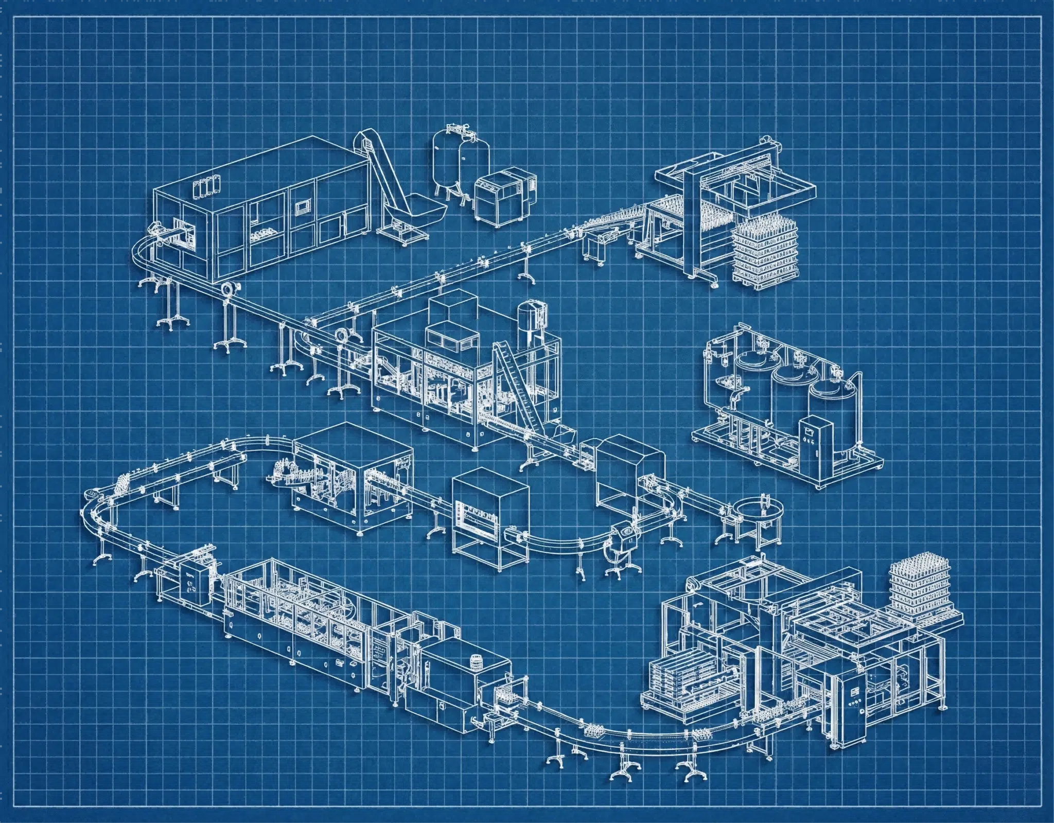
iBottler provides a comprehensive CAD layout service. We take your building dimensions and map out the machine placement, piping routes, and auxiliary equipment locations to ensure a plug-and-play installation experience.
This is where the difference between a "machine seller" and a "partner" becomes clear. At iBottler, we do not just ship a container and wish you luck. Before you finalize your order, I ask for a simple sketch of your factory with dimensions. I need to know where the doors are, where the main power enters the building, and where the drains are located.
Our engineering team then creates a detailed layout plan. We position the high-pressure compressor, the chiller, and the conveyor lines. We calculate the pipe lengths you will need. We check the maintenance clearances to ensure the "1.5m rule" is met. We even simulate the flow of the operator to ensure they can work comfortably without walking unnecessary miles every day.
This service eliminates the panic of the installation day. You know exactly where to pour the concrete foundation and where to run the cables before the truck arrives. If you are developing a new bottle, we can even integrate this with our PET bottle mold design guide to ensure your production line matches your product strategy perfectly. We build the factory in the computer so you don't make mistakes in reality. We also plan for your future. If you tell us "I want to add two more machines in 3 years," we will design the piping and cable trays now to handle that capacity, saving you from ripping everything out later.
| Service | Standard Seller | iBottler |
|---|---|---|
| Layout Planning | None / Generic PDF | Custom CAD for your building |
| Utility Calculation | "Check manual" | Specific cable/pipe sizing provided |
| Workflow Optimization | Ignored | Logistics flow integrated |
| Installation Support | Remote only | Pre-arrival engineering guide |
Conclusion
Planning your factory layout is as important as choosing the machine. Proper spacing, power stability, and piping design prevent costly downtime. It is the foundation upon which your production efficiency is built. If you cut corners on the layout, you will pay for it every day in lost efficiency and higher maintenance costs. Plan first, build once.
Frequently Asked Questions
1. How much total space do I need for a standard 4-cavity blow molding line?
While the machine itself may be small (e.g., 5m x 2m), a complete line with the high-pressure compressor, air tank, chiller, cooling tower, and necessary working space typically requires a minimum area of 80-100 square meters. You also need to account for storage space for preforms and finished bottles, which often takes up more space than the machines themselves.
2. Can I use my existing low-pressure air compressor for the blowing machine?
No. PET blowing requires high pressure (25-30 Bar) to expand the plastic into the mold details. Standard factory compressors only provide 7-8 Bar, which is only enough for the machine's mechanical movements (like clamping and stretching), not for blowing the bottles. You will need a dedicated high-pressure booster or a specialized high-pressure compressor.
3. Do I really need a chiller if I am in a cold country?
Yes. The chiller is not for the room; it is for the mold. Even if the air is cold, the process generates heat. You must actively remove heat from the mold steel to keep the cycle time fast (e.g., 2000 bottles per hour). Without a chiller, the mold overheats, and bottles will stick to the metal or deform upon ejection.
4. What happens if I don't use a voltage stabilizer?
You risk burning out the servo drivers and PLC. In many warranty terms, damage caused by external power surges is explicitly excluded. A stabilizer is a small insurance premium to protect a large investment. If your voltage is stable (e.g., in a high-tech industrial park), you might skip it, but in most cases, it is highly recommended.
5. Can iBottler help me if I have a very oddly shaped building?
Yes. This is our specialty. We can design "L-shape" or "U-shape" production lines to fit into tight or irregular spaces while maintaining logical workflow and safety standards. We can also design flexible conveyor systems that move bottles around pillars or obstacles.
Factory Planning Checklist
| Category | Key Requirement | Why it Matters |
|---|---|---|
| Space | 1.5m Perimeter Clearance | Maintenance access and mold changing. |
| Height | Loader Height + 0.5m | Prevents cutting holes in your roof. |
| Power | Voltage Stabilizer | Protects expensive servo electronics. |
| Air | Ring Main Piping | Maintains consistent pressure at the mold. |
| Water | Outdoor/Ventilated Chiller | Prevents factory overheating. |
| Floor | Reinforced Concrete | Prevents vibration damage. |
| Temperature | Oven Exhaust Hood | Extends electrical component life. |
