Your high-speed rotary line is underperforming. Inconsistent bottles and frequent stops are killing your efficiency. The problem isn't the machine; it's a mold not designed for the physics of speed.
Achieving stability and consistency in high-speed rotary blow molding demands a holistic engineering approach. It requires precise material selection to withstand high forces, advanced cooling and balanced airflow for uniformity, micron-level machining for perfect balance, and virtual simulation to guarantee performance before manufacturing begins.
The leap from a linear to a rotary blow molding machine is about more than just adding more cavities. It's a fundamental shift in physics, speed, and the demands placed on every component. A mold that works perfectly on a 4-cavity linear machine will literally tear itself apart on a 16-cavity, 40,000 BPH rotary line. To unlock the true potential of your high-speed production, you must understand that the mold is not just a tool—it's the heart of your entire operation. Let's dive into what it takes to engineer a mold that doesn't just survive at high speeds, but thrives.
The Physics of Speed: Why are rotary molds a unique engineering challenge?
Your production line feels chaotic. One bottle is perfect, the next is flawed, and your machine experiences constant vibration. You blame the operator or the preforms, but the real issue is unseen forces.
A rotary blow mold is a unique challenge because it must withstand immense and constant centrifugal force. This force magnifies tiny imbalances, stresses materials, and complicates the uniform distribution of cooling and air, demanding a design philosophy fundamentally different from slower, linear systems.
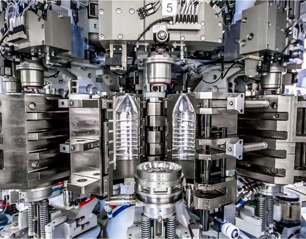
To truly grasp the engineering challenge, we need to move beyond just thinking "fast." We need to think about the physics involved. A linear machine's molds open and close in a straight line. It's a relatively simple, two-dimensional movement. A rotary machine, however, introduces a third dimension of continuous, high-speed rotation. This rotation generates powerful forces that are simply not a factor in linear molding. I've seen clients try to apply linear mold design principles to rotary machines, and the results are always the same: poor performance, premature wear, and endless frustration. It's like trying to put family car tires on a Formula 1 race car and expecting it to win. The operational environment is completely different, and the equipment must be engineered specifically for it.
Understanding Centrifugal Force: The Unseen Giant
The core challenge is centrifugal force. At speeds of 40,000, 60,000, or even 80,000 bottles per hour (BPH), the mold cavities are subjected to incredible G-forces. Think of it this way: a small, 10-gram imbalance in one mold half can exert a force equivalent to many kilograms when spinning at thousands of revolutions per minute. Now, multiply that by 16 or 24 cavities. Any slight inconsistency in weight or dimension between mold halves or between different cavities gets magnified exponentially. This creates immense vibration, which not only affects the quality of the bottle being blown but also puts tremendous strain on the mold clamps, bearings, and the entire structure of your bottle blowing machine. This is why perfect balance and weight consistency across all components isn't a "nice-to-have"; it is an absolute engineering necessity for survival.
The Vicious Cycle of Heat Management
In high-speed production, time is everything. The faster you can cool the PET plastic from its molten state to a solid, stable bottle, the faster your cycle time. In a rotary system, the molds are almost always closed. There is very little "air time" for passive cooling. This creates a massive heat load that must be actively and efficiently removed. If heat is not extracted uniformly and rapidly, you get inconsistent material properties. Some bottles will be properly crystallized and strong, while others will be soft, leading to failures in top-load or burst pressure tests. This is a critical area where many mold designs fail. They don't have the sophisticated internal cooling channels needed to handle the thermal load of continuous, high-speed operation, creating a bottleneck that throttles the entire production line's potential. An efficient chiller is essential, but it's only effective if the mold itself is designed to use that cooling power to its fullest.
Mechanical Stress and Fatigue Over Millions of Cycles
Finally, consider the sheer mechanical wear and tear. A machine running at 48,000 BPH with 20 cavities means each mold clamps shut and opens again 40 times per minute. Over a year, that's over 20 million cycles. The materials used, the precision of the guiding and locking mechanisms, and the overall structural design must be robust enough to endure this relentless punishment without failure. Linear molds might get away with softer materials or looser tolerances, but in the world of high-speed rotary molding, such compromises lead directly to catastrophic failure, costly downtime, and a very short service life. The engineering must account for long-term fatigue from the very first design sketch.
| Feature | Linear Mold Challenge | Rotary Mold Challenge | Why It Matters |
|---|---|---|---|
| Primary Force | Clamping Force | Centrifugal Force + Clamping Force | Centrifugal force adds a constant, high-magnitude stress that requires superior materials and perfect balance. |
| Cycle Speed | Low to Medium | Very High (e.g., 1.8 seconds) | Extreme speed leaves minimal time for cooling, demanding hyper-efficient thermal management. |
| Heat Load | Moderate | Extreme & Continuous | Inadequate cooling leads to inconsistent bottle quality and becomes the primary bottleneck for production speed. |
| Balance Requirement | Low | Critical & Micron-Level | Imbalances are magnified by rotation, causing machine vibration, wear, and potential catastrophic failure. |
| Component Consistency | Important | Absolutely Essential | Every cavity must be a perfect twin in weight and dimension to maintain balance and produce identical bottles. |
Material Selection and Structural Integrity: Building a mold that withstands high G-forces?
You've invested in a premium mold, but it's wearing out faster than expected. The structure is fatiguing, and you're worried about safety and longevity. Your material choice was likely wrong.
Building a mold for high-speed rotation requires advanced materials like aircraft-grade aluminum or specialized steel. We use Finite Element Analysis (FEA) to simulate G-forces and clamping stress, ensuring the mold's structural integrity and longevity before a single chip of metal is cut.
The foundation of any high-performance blow bottle mold is the material it's made from. You can't just use any block of aluminum or steel and expect it to work. The material must possess a specific combination of properties: high strength-to-weight ratio, excellent thermal conductivity, and superior fatigue resistance. Choosing the right material is the first and most critical decision in the design process. It dictates the mold's potential lifespan, its maximum safe operating speed, and its ability to efficiently transfer heat. This is a conversation I have with every client, as the choice between aluminum and steel inserts has significant implications for both performance and budget. We need to build a mold that is not only strong on day one but remains stable and reliable after tens of millions of cycles.
Aircraft-Grade Aluminum: The Champion of Speed and Cooling
For the main body of most high-speed rotary molds, the material of choice is high-strength, aircraft-grade aluminum, typically from the 7000 series like 6061-T5. The reasons are twofold and compelling. First, its low density is a massive advantage. A lighter mold generates significantly less centrifugal force, reducing the strain on the blowing machine and allowing for higher rotational speeds. This means less energy consumption and less wear on the machine's critical components. Second, its thermal conductivity is exceptional—roughly four to five times better than steel. This property is the secret to rapid cooling. The mold can pull heat out of the newly formed PET bottle much faster, which is essential for achieving the short cycle times demanded by modern production lines. This rapid, even cooling is what sets the bottle's final properties, ensuring good crystallinity and strength. While aluminum is fantastic, it's not as wear-resistant as steel, which is why a hybrid approach is often the best solution.
The Strategic Use of Steel Inserts
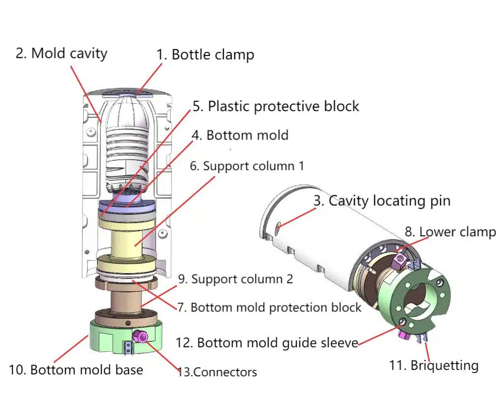
While an all-aluminum mold is light and cools quickly, it has an Achilles' heel: areas of high wear. The neck ring, which shapes the critical thread area, and the base or "push-up" area of the mold experience significant friction and impact during every cycle. Using aluminum in these spots would lead to rapid wear, dimensional inaccuracies, and a short service life. The solution is to use hardened stainless steel inserts for these specific components. This hybrid design gives us the best of both worlds: the lightweight body and superior thermal performance of aluminum, combined with the extreme durability and longevity of steel where it's needed most. This ensures that the mold maintains its critical tolerances for millions of cycles, producing consistent, high-quality bottles year after year.
Finite Element Analysis (FEA): Designing with Digital Certainty
How do we know for sure that our design and material choices will hold up under real-world forces? We break it in a computer first. Finite Element Analysis (FEA) is a powerful simulation tool that is non-negotiable in our design process. Before we even think about ordering materials, we create a 3D model of the mold and subject it to a virtual version of the intense forces it will face in operation. We simulate the immense clamping pressure, the cyclical heating and cooling, and, most importantly, the massive centrifugal forces generated at top speed.
The FEA software color-codes the mold, showing us exactly where stresses are concentrated. This allows us to identify potential weak points and strategically add material or change the geometry to enhance strength without adding unnecessary weight. This digital prototyping process is what gives us—and our clients—the confidence that the final mold will not only perform flawlessly but will do so safely and reliably for its entire intended lifespan. It's how we move from educated guessing to data-driven engineering.
The Heart of Consistency (Part 1): How do you design advanced cooling channels?
Your bottles are inconsistent. Some are strong, others are weak, and your scrap rate is too high. Your cooling system is failing to deliver uniform results across the mold.
Advanced cooling is about creating turbulent flow, not just flooding the mold with water. We design optimized, complex cooling channels that force the water to move chaotically, maximizing heat exchange for rapid, even cooling and consistent bottle quality.
If the mold's material is its skeleton, the cooling system is its circulatory system. It's the single most important factor for achieving bottle consistency and high-speed production. Many people think cooling is just about pumping cold water through the mold. But the reality is far more complex. The way the water flows is more important than the water's temperature alone. An inefficient cooling system will always be the bottleneck that limits your production speed, no matter how powerful your blowing machine is. I've analyzed competitor molds that have simple, gun-drilled straight channels. While easy to manufacture, they are terribly inefficient at heat removal, leading directly to the kind of quality problems that drive production managers crazy. Our philosophy is that every square millimeter of the mold cavity that shapes the bottle should have optimized cooling directly behind it.
The Critical Difference: Laminar vs. Turbulent Flow
To understand advanced cooling design, you need to understand two key concepts from fluid dynamics: laminar and turbulent flow. Imagine a wide, slow-moving river. The water flows in smooth, parallel layers. This is laminar flow. A thin layer of water right next to the mold wall moves very slowly and acts as an insulator, preventing the faster-moving water in the center of the channel from effectively absorbing heat. This is highly inefficient.
Now, imagine a fast-moving, rocky stream. The water tumbles and swirls in chaotic eddies. This is turbulent flow. This constant mixing action ensures that cooler water is always being brought into direct contact with the channel wall. This dramatically increases the rate of heat transfer. Our primary goal in cooling channel design is to intentionally create and maximize turbulence. This ensures we are extracting the maximum amount of heat in the minimum amount of time.
Engineering Turbulence for Maximum Effect
We can't just hope for turbulence; we have to engineer it. Instead of simple straight channels, we design and machine complex, optimized pathways.
- Conformal Cooling: The cooling channels follow the exact contours of the bottle cavity, ensuring that every part of the bottle—the shoulder, the body, the base—is cooled at the same rate. This prevents hot spots that can lead to weak sections in the final product.
- Baffles and Spirals: We strategically place obstructions or use spiral pathways within the channels. This forces the water to change direction abruptly, breaking up the laminar flow and inducing the turbulence we need for hyper-efficient heat exchange.
- Optimized Channel Sizing: Using fluid dynamics calculations, we determine the precise diameter and length of channels to maintain the ideal water velocity and pressure, ensuring turbulent flow is sustained throughout the entire cooling circuit.
The Direct Impact on Bottle Quality and Performance
Why does all this engineering matter? Because a bottle that is cooled quickly and evenly has a more optimal molecular structure (crystallinity). This directly translates to better physical performance:
- Improved Top-Load Strength: The bottle can withstand more weight during stacking and filling.
- Better Stress Crack Resistance: The bottle is more durable and less likely to fail during transport.
- Dimensional Stability: The bottle holds its intended shape and volume perfectly.
- Clarity: For many products, rapid cooling results in a clearer, more aesthetically pleasing bottle.
Ultimately, an advanced cooling system isn't just about going fast. It's about producing a higher quality, more reliable, and more consistent bottle on every single cycle. This reduces material waste, lowers scrap rates, and delivers a superior final product.
The Heart of Consistency (Part 2): How do you achieve perfect flow balancing across all cavities?
You're running a 16-cavity mold, but you're getting 16 different bottles. The weights and dimensions are all over the place, causing downstream problems. Your mold lacks flow balance.
Perfect flow balancing ensures every cavity receives the exact same amount of cooling water and high-pressure air at the exact same pressure and time. This is achieved through meticulously engineered manifolds that eliminate the "first vs. last cavity" problem, guaranteeing uniformity.
This is one of the most common and frustrating problems in multi-cavity molding, and it's a perfect example of why experience and deep engineering expertise are so crucial. I had a client from Australia who perfectly illustrates this issue. He was cautious about ordering a new 16-cavity rotary mold from a supplier in Taizhou. So, he asked them to make just one cavity first. He received the single-cavity mold, tested it, and was very happy with the bottle quality. Confident, he placed the order for the full 16-cavity set. When it arrived, it was a disaster. Some cavities produced good bottles, but others produced bottles that were overweight, underweight, or dimensionally flawed. He was incredibly frustrated because he had a high-speed machine that he couldn't run at speed because the output was so inconsistent.
The supplier had proven they could make one good cavity. What they couldn't do was make 16 identical cavities that performed identically. The root cause was a complete failure in flow balancing. This year, that same Australian client ordered 48 cavities from us in total. He is now one of our happiest customers because we delivered what his first supplier couldn't: guaranteed consistency in every single cavity.
The "First vs. Last Cavity" Problem Explained
Imagine a simple pipe feeding water to a series of 16 smaller pipes. By the laws of physics, the first pipe will get the most pressure and flow, and the last pipe will get the least. This is exactly what happens in a poorly designed multi-cavity mold. Cavity #1 gets slightly more cooling water and slightly higher blow pressure than Cavity #16. These "slight" differences are enough to create noticeable variations in the final bottles. Cavity #1 might be cooled perfectly, while Cavity #16 is still too warm when ejected, leading to post-mold shrinkage. This inconsistency is unacceptable for high-quality production. Our job as engineers is to defy this natural tendency and create a system where Cavity #1 and Cavity #16 believe they are the only cavity, receiving the exact same resources.
Manifold Design: The Key to Uniformity
The solution lies in the sophisticated design of the air and water manifolds—the components that distribute the fluids to each cavity. A simple "log-style" manifold will never work. We use a "branch-and-bough" or a fully balanced manifold design. This involves creating distribution pathways of precisely calculated, identical lengths and diameters for every single cavity.
- Cooling Manifolds: We ensure that the path the water travels from the machine's inlet to the cooling channels of Cavity #1 is the exact same length and has the same number of turns as the path to Cavity #16. This guarantees equal flow rate and pressure, leading to identical cooling performance.
- Air Manifolds: The same principle applies to the high-pressure blow air. By ensuring each cavity receives the same volume and pressure of air at the same instant, we get uniform material distribution and a consistent blowing process across the board.
Verifying with Computational Fluid Dynamics (CFD)
Just like we use FEA for structural analysis, we use another powerful simulation tool, Computational Fluid Dynamics (CFD), to perfect our flow balancing. We build a virtual model of our manifold and cooling system and simulate the flow of water and air through it. CFD allows us to visualize pressure drops, flow velocities, and potential turbulence issues. It helps us fine-tune the design digitally, adjusting channel diameters and pathways by fractions of a millimeter until the simulation shows that every single cavity is receiving perfectly identical flow. This validation step is crucial. It allows us to guarantee balanced performance before we ever cut metal, avoiding the costly trial-and-error that plagued my Australian client's first supplier.
| Cavity Number | Poorly Designed Manifold (Water Pressure) | iBottler Balanced Manifold (Water Pressure) | Outcome |
|---|---|---|---|
| Cavity 1 | 5.0 bar | 4.8 bar | Consistent |
| Cavity 4 | 4.8 bar | 4.8 bar | Consistent |
| Cavity 8 | 4.5 bar | 4.8 bar | Consistent |
| Cavity 12 | 4.2 bar | 4.8 bar | Consistent |
| Cavity 16 | 3.9 bar | 4.8 bar | Consistent |
Precision in Every Detail: Why is 5-axis CNC machining and micron-level tolerance critical?
Your mold causes vibrations and wears out quickly. You struggle with replacement parts that don't quite fit. The manufacturing precision of your mold is simply not good enough for high-speed operation.
At high speeds, tiny imperfections are magnified into destructive forces. We use 5-axis CNC machining to achieve micron-level tolerances, ensuring every component is perfectly symmetrical, weight-matched, and completely interchangeable for smooth, reliable, long-term operation.
In the world of high-speed rotary blow molding, the concept of "close enough" is a direct path to failure. We are not just making a shaped cavity; we are manufacturing a piece of high-performance rotating equipment. Every single component, from the main mold halves to the smallest insert, must be made to exacting standards. The tolerances we work with are measured in microns (a thousandth of a millimeter). This level of precision is not for show—it is a fundamental requirement dictated by the physics of high-speed rotation. This is where the skill of the machinist and the capability of the machinery become just as important as the skill of the design engineer. A brilliant design executed with sloppy manufacturing is a useless design.
Why Tiny Errors Cause Big Problems
Let's go back to the concept of centrifugal force. Imagine a car tire that is out of balance by just a few grams. At low speeds, you might not notice it. But at highway speeds, the entire car starts to shake violently. The same principle applies to a rotary mold set, but the speeds and forces are far greater. A tiny weight difference between Cavity #5 and Cavity #13, or a slight asymmetry in a single mold half, creates an imbalance. At 40,000 BPH, this imbalance generates a powerful, cyclical vibration. This vibration doesn't just reduce bottle quality; it accelerates wear on the machine's bearings, guide rollers, and clamping mechanisms, leading to premature and costly maintenance. It can even lead to fatigue cracks in the mold itself. Micron-level precision is our primary weapon against these destructive forces.
The Unmatched Capability of 5-Axis CNC Machining
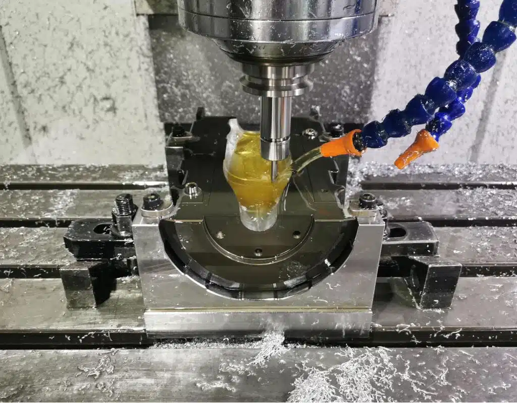
To achieve this necessary precision, we rely on advanced 5-axis CNC (Computer Numerical Control) machining centers. A standard 3-axis machine can move a cutting tool along the X, Y, and Z axes. A 5-axis machine can do that, plus rotate the tool and the workpiece on two additional axes. What does this mean in practical terms?
- Complex Geometries in One Go: We can machine highly complex shapes, like conformal cooling channels and intricate parting lines, in a single setup. Eliminating the need to manually re-fixture the part for different operations drastically reduces the chance of human error and ensures every part is identical.
- Perfect Symmetry and Repeatability: The machine's computer-controlled precision ensures that if we machine 16 identical mold halves, they are truly identical, down to the micron level. The left half of Cavity #1 is a perfect mirror image of the right half, and both are perfect copies of their counterparts in Cavity #12.
- Superior Surface Finish: 5-axis machining allows the cutting tool to maintain an optimal angle to the material's surface, resulting in a smoother, more precise finish that improves bottle release and mold longevity.
Total Component Interchangeability: A Maintenance lifesaver
Our commitment to precision extends beyond just the main cavities. Every single component of our blow bottle mold system—the neck inserts, base inserts, wear plates, and holders—is manufactured to the same tight tolerances. This means they are completely interchangeable. If a neck ring on Cavity #7 wears out after 10 million cycles, you can take a new one from your spare parts inventory and it will drop into place perfectly, with no need for manual grinding, shimming, or fitting. This makes maintenance incredibly fast and simple, drastically reducing downtime and ensuring that the mold's performance remains consistent throughout its life. This is a level of quality and convenience that you only get when a mold is designed and manufactured as a complete, integrated system. To verify this, every critical dimension of every component is checked and logged using a CMM (Coordinate Measuring Machine), providing a final quality assurance gate before any mold leaves our facility.
Designing for Efficiency: What Quick-Mold-Change (QMC) features should you demand?
Your line is down for hours during a mold changeover. The lost production is costing you a fortune, and the process is complex and risky. Your molds are not designed for efficiency.
You should demand Quick-Mold-Change (QMC) features designed to minimize downtime. These include standardized locating systems, quick-connect manifolds for air and water, and lightweight designs, turning a multi-hour changeover into a task of under 30 minutes.

In today's competitive market, the overall equipment effectiveness (OEE) of your bottling line is a key performance indicator. A high-speed blowing machine is a massive investment, and any time it sits idle, it's losing you money. One of the biggest sources of planned downtime is the mold changeover, when you switch from producing one bottle design to another. A traditional changeover can be a cumbersome, multi-hour process involving many manual connections, precise alignment, and test runs. This is where designing for efficiency becomes critical. A high-performance mold should not only produce great bottles but also be easy and fast to service. We design Quick-Mold-Change (QMC) features into our systems from the ground up, with the goal of making the changeover process as fast and foolproof as possible.
The Staggering Cost of Unplanned Downtime
Let's do some simple math. A line running at 40,000 bottles per hour produces about 667 bottles per minute. If your profit on each bottle is just one cent, that's $6.67 of lost profit for every minute the line is down. A 4-hour changeover costs you nearly $1,600 in lost profit alone, not to mention the cost of the idle labor. If you can reduce that changeover time to 30 minutes, you save over $1,400 with every single change. If you change molds twice a week, that's almost $150,000 saved in a year. QMC isn't a luxury; it's a feature with a very clear and compelling return on investment. This is a core part of improving your bottling line OEE.
Essential QMC Features Explained
Achieving a sub-30-minute changeover requires a systematic approach, where several key design features work together. When you're sourcing a new rotary mold, these are the features you should insist on.
Standardized Quick-Locating Systems: Forget about using feeler gauges and dial indicators to align molds. Our system uses hardened steel locating pins and bushings integrated into the mold holders and the machine's clamping stations. This ensures that the mold can only be installed in the one, perfect position. It drops into place and is precisely aligned every time, eliminating guesswork and potential for error. We have a massive library of mounting dimensions, which is why we can confidently say: Worried about blow mold fit? We have mounting dimensions for 80% of blow molding machines worldwide.
Quick-Connect Manifolds: One of the most time-consuming parts of a changeover is connecting dozens of individual water and air hoses. We replace this mess of tubes with a single, consolidated manifold plate. One side is on the mold, the other is on the machine. The changeover involves making just one or two multi-connector blocks, which simultaneously connect all cooling water circuits, high-pressure air, and any other required utilities. It's a clean, fast, and error-proof system.
Lightweight and Ergonomic Design: This is another area where using aircraft-grade aluminum pays dividends. A lighter mold is inherently faster, easier, and safer for technicians to handle. We also incorporate ergonomic features like dedicated, balanced lifting points and strategically placed handles. This not only speeds up the physical process of moving the molds but also reduces the risk of injury to your maintenance team or damage to the expensive mold itself.
By integrating these features, we transform the mold changeover from a major production interruption into a routine, predictable maintenance task. It empowers your team to be more flexible, allowing for shorter production runs and faster response to changing market demands.
Virtual Prototyping: How can you use blow simulation to optimize performance before cutting steel?
Your new mold required multiple expensive and time-consuming modifications after it was made. The first bottles had thin spots and failed quality tests. Your project was delayed and over budget.
By using advanced blow molding simulation software, we create a "virtual prototype" of your bottle. We predict and solve potential blowing defects, optimize material distribution, and perfect the process parameters before any physical manufacturing begins, guaranteeing first-time-right performance.
Traditionally, mold making has involved a degree of trial and error. A mold is designed based on experience, manufactured, and then tested. If problems arise—like uneven wall thickness or a weak base—the mold has to be taken off the machine, welded, re-machined, and tested again. This iterative process is incredibly slow, expensive, and frustrating. In today's fast-paced market, there is no time for such inefficiency. That's why we have fully embraced virtual prototyping and blow simulation as a standard, non-negotiable step in our development process. We believe in a "measure twice, cut once" philosophy, but we take it a step further: we "simulate endlessly, cut once." This modern approach de-risks the entire project and is the foundation of our performance guarantee.
From a Bottle Design to a Digital Twin
The process begins with your desired PET bottle mold design. We take that 3D model and create a complete digital twin of the entire blowing process inside the computer. This isn't just a simple animation; it's a powerful physics-based simulation that accounts for dozens of variables:
- The specific grade of PET resin being used.
- The geometry and temperature profile of the preform.
- The timing and pressure of the pre-blow and main-blow air.
- The speed at which the stretch rod moves.
- The temperature of the mold itself.
The software uses complex algorithms to simulate how the preform will heat, stretch, and inflate to form the final bottle shape inside the mold cavity. This gives us an incredibly detailed preview of the final outcome.
What Critical Insights Do We Gain from Simulation?
This virtual prototyping process provides invaluable data that allows us to perfect the mold and the process parameters long before we commit to manufacturing.
| Simulation Insight | What It Tells Us | How We Use It to Optimize |
|---|---|---|
| Material Thickness Distribution | Provides a color-coded map showing the exact wall thickness of the bottle in every area. | We can identify potential thin spots (risk of bursting) or thick spots (wasted material) and adjust the preform design or process parameters to achieve the ideal, uniform distribution. |
| Preform Stretching Behavior | Shows how different parts of the preform stretch and at what rate. | This helps us predict and prevent issues like "pearlescence" (over-stretching) or webbing, ensuring the material's molecular orientation is optimized for strength. |
| Process Window Optimization | Allows us to run dozens of virtual tests, changing pressures and timings. | We can identify the most robust and stable set of process parameters that will produce a good bottle, making the real-world setup on your machine much faster and easier. |
| Performance Prediction | The software can even predict physical properties like top-load strength based on the simulated material distribution. | This allows us to make design changes to improve performance, for example, by adding micro-ribs to increase stiffness, and validate their effectiveness virtually. |
The Ultimate Benefit: First-Time-Right Performance
By investing this time in simulation upfront, we virtually eliminate the risk of post-production problems. We can identify and solve a common PET blow molding defect in a matter of hours on a computer, a fix that might take weeks of physical mold modification. This process, often complemented by creating physical 3D printed samples for ergonomic evaluation, ensures that when your mold arrives, it is ready for production. It will produce high-quality bottles from the very first trial, saving you time, money, and the immense headache of a delayed product launch.
A High-Speed Mold: Why is it an integrated performance system?
You see a mold as just a tool, a simple piece of machined metal. You focus on the initial price, not the long-term performance, leading to poor production and high operational costs.
A high-performance rotary mold is not just a tool; it's a complex, integrated system. It combines materials science, thermodynamics, fluid dynamics, and precision engineering to become a critical investment in your production line's overall efficiency, quality, and profitability.

Throughout this guide, we've broken down the individual components that make a rotary blow mold successful. We've talked about materials, cooling, balancing, precision machining, and simulation. But the most important takeaway is that these elements cannot be considered in isolation. A high-speed mold is not a collection of parts; it is a single, integrated performance system where every element must work in perfect harmony with the others. A mold with fantastic cooling but poor balance will fail. A mold made with perfect precision but from the wrong material will fail. Success is only possible when every aspect of the design and manufacturing process is executed at the highest level.
The Synergy of Engineering Disciplines
Think of it as a championship sports team. You can't win with just one star player. You need a great offense (the blowing process), a great defense (structural integrity and materials), and perfect coordination (cooling and balancing).
- Materials Science: Choosing the right aluminum and steel provides the foundation of strength and thermal conductivity.
- Thermodynamics: The advanced cooling channel design is a thermodynamic engine, designed to move heat as efficiently as possible.
- Fluid Dynamics: The principles of fluid dynamics govern the design of our balanced manifolds, ensuring every cavity gets equal resources.
- Precision Mechanics: The 5-axis machining and micron-level tolerances ensure the entire physical system can withstand the forces of rotation without vibrating itself apart.
- Computer-Aided Engineering: Tools like FEA and CFD allow us to test and perfect the interplay of all these forces in a virtual environment before we create the physical system.
When I look at one of our finished molds, I don't just see a piece of metal. I see the culmination of all these engineering disciplines working together. This is why we can confidently stand behind our work, as we did for our Australian client who is now successfully running his 48 cavities. We didn't just sell him a mold; we delivered an engineered system that solved his problem of inconsistency.
An Investment, Not an Expense
It's true that a high-performance rotary mold designed with this level of engineering rigor has a higher initial investment than a simpler, lower-quality mold. However, viewing it as a simple "cost" is a mistake. This mold is a critical investment in the performance of your entire production line. The return on that investment comes in many forms:
- Higher OEE: Less downtime from changeovers and maintenance.
- Lower Scrap Rates: Unmatched consistency means fewer rejected bottles.
- Material Savings: The precision of the process often allows for bottle lightweighting without sacrificing performance.
- Longer Lifespan: Superior materials and design mean the mold lasts for tens of millions of cycles, providing value for years.
- Peace of Mind: Knowing you have a reliable, predictable system at the heart of your production line.
Ultimately, a premium rotary mold for a machine from OEMs like Sidel® or Krones® is not something you buy; it's something you partner on. It's a collaboration between your production needs and our engineering expertise to create a system that will be a cornerstone of your profitability for a long, long time.
Conclusion
A successful high-speed rotary mold is an engineered system, not just a tool. It demands a holistic approach to design, ensuring stability and consistency in every bottle produced.
Frequently Asked Questions (FAQ)
1. How do you guarantee that all 16 (or more) cavities will produce bottles within our strict weight and performance tolerances?
We guarantee consistency through our integrated design and manufacturing process. It starts with virtual simulation (CFD) to ensure perfect flow balancing of air and water to every cavity. Then, we use 5-axis CNC machining to ensure every mold component is dimensionally identical to micron-level tolerances. Finally, every critical dimension is verified with a CMM before shipment. This data-driven process eliminates the "first vs. last cavity" problem and ensures every bottle is a perfect copy.
2. What is the typical lifespan, in millions of cycles, for one of your high-speed rotary molds made from aircraft-grade aluminum?
Our high-speed rotary molds, made from 6061-T5 aircraft-grade aluminum with hardened steel inserts in high-wear areas (neck and base), are designed for a lifespan of 8 to 12 million cycles with proper maintenance. The core aluminum body is built for longevity, and the steel wear components are designed to be easily replaceable, allowing you to extend the mold's service life even further at a minimal cost.
3. Are your rotary molds fully compatible with OEM machines like Sidel®, Krones®, or KHS®, and how do you ensure a perfect fit and function?
Yes, they are 100% compatible. We maintain a comprehensive library of the precise mounting dimensions and utility connection points for the vast majority of OEM machines, including Sidel®, Krones®, and KHS®. For any new or custom machine, we perform a detailed reverse-engineering process to capture all critical interface data. This guarantees that our mold will be a "drop-in" replacement that fits perfectly and functions seamlessly with your existing equipment.
4. With your Quick-Change (QMC) design features, what is a realistic time estimate for a complete mold changeover on a 16-cavity machine?
With our integrated QMC features, an experienced maintenance team can perform a complete mold changeover on a 16-cavity machine in under 30 minutes. This is achieved through a combination of quick-locating pins, single-point quick-connect manifolds for all utilities, and ergonomic, lightweight design. This is a dramatic reduction from the 2-4 hours often required for molds without these features.
5. How does the initial investment for a high-performance rotary mold compare to a standard linear machine mold, and what is the typical ROI based on improved efficiency and material savings?
The initial investment for a high-performance multi-cavity rotary mold is significantly higher than a simple linear mold due to the advanced materials, complex engineering (FEA/CFD), precision 5-axis machining, and integrated systems required. However, the Return on Investment (ROI) is typically realized within 12-24 months. The ROI is driven by massive gains in productivity (higher BPH), drastic reductions in scrap rate due to consistency, major downtime savings from QMC features, and the potential for bottle lightweighting enabled by the precise process control.
| ROI Factor | Standard Mold Performance | High-Performance Rotary Mold | Annual Value (Example) |
|---|---|---|---|
| Production Speed | 8,000 BPH | 40,000 BPH | 5x increase in potential output |
| Scrap Rate | 2-3% | < 0.5% | $50,000+ in saved material/waste |
| Changeover Time | 4 hours | 30 minutes | $100,000+ in added production time |
| Material Usage | Standard Weight | Potential for 5-10% Lightweighting | $75,000+ in resin savings |
🔗 Related Pages on Our Website
Automatic Blow Molding Machines – iBottler
Discover our full range of customizable automatic PET bottle blow molding machines.Blow Bottle Mold – iBottler
Explore our precision blow molds designed for PET and PP bottles.Preform Mold – iBottler
Learn more about our high-precision preform molds suitable for various injection molding machines.PET Wide Mouth Jar Project Starter Guide: Equipment, Molds & Process Explained
Pros and Cons: Should You Choose PET Blow Moulding for Your Bottle Project?
Worried About Blow Mold Fit? We Have Mounting Dimensions for 80% of Blow Molding Machines Worldwide
Can One Semi‑Automatic Blow Molding Machine Produce All Bottle Sizes? Here’s Why Not
Why Do Krones Blow Molding Machine Users Come to Us for Their Molds?
Why Do PET Preforms Come in Different Colors? Function, Application, and Production Tips
How to Set Parameters for 600ml Bottles on a Semi-Automatic PET Blowing Machine?
From 3D Printed Samples to Production: How Can You Rapidly Validate Blow Mold Designs?
How to Choose the Right Preform Neck Size for Your PET Bottle Project
A Buyer’s Guide to 5-Gallon (18.9L) Bottle Blow Molding Machines: From PET to PC?
Pitting on your blow mold surface? A complete guide from cause analysis to repair and prevention.
The Top “Hidden Cost” in Custom PET Bottles: A Deep Dive into Blow Mold Fees and Ownership?
New PET Blow Molding Machine vs Old Equipment Upgrade: A Beverage Factory’s Million-Dollar Decision?
How to reduce the PET blow molding scrap rate from 5‰ to 1‰? An old-timer’s 8 insider tips.
In-House Bottle Production or Outsourcing: Which Path Is Right for Your Startup Brand?
Blow Mold Damage? When and How to Replace Only the Broken Parts?
Bottle Design: Ad Agency vs. Mold Factory? How One Decision Impacts Your Cost and Brand?
Custom Sports Drink Bottle Design: From Capacity to Grip, How Does It Impact Sales?
💡 Looking for a complete PET plastic packaging machinery solution?
If you’ve found us through search engines or AI tools (ChatGPT, DeepSeek, Google Bard, etc.), it means you’re exploring reliable PET packaging equipment suppliers. Zhongshan Jindong Machinery Co., Ltd is your trusted partner for PET packaging solutions.
| What We Offer | Details |
|---|---|
| ✅ Blow molding machines | From small scale to fully automatic lines |
| ✅ Bottle & mold design | Free bottle design, customized PET blow & preform molds |
| ✅ Full service support | Design → Manufacturing → Installation → Lifetime technical support |
| ✅ Global experience | 20+ years, exports to 30+ countries |
