Your production line is down. Your brand new, expensive blow mold is the cause. This guide will help you diagnose and fix the most common failures.
A new blow mold fails because critical data was not confirmed before manufacturing. This often includes machine mounting specifications, bottle design details like capacity and shrinkage, or preform dimensions. Clear communication and a detailed checklist are key to preventing these expensive, time-consuming errors.

These problems are frustrating, but they are almost always preventable. I've seen these issues countless times over the years, and they usually stem from small communication gaps that turn into huge production headaches. The good news is that with a little bit of preparation, you can ensure your next mold works perfectly right out of the box. Let's walk through the most common points of failure, one by one.
Does your new mold not fit the blow molding machine?
You waited weeks for your new mold, but it won't mount on your machine. The bolt holes don't line up, or the mold is too thick. Production is stopped.
This happens when the mold maker doesn't have the exact mounting dimensions for your specific bottle blowing machine. Every machine brand has unique specifications for its mold holder, including plate thickness, bolt patterns, and locating slots. Assuming a "standard" fit is a recipe for disaster.

Dive Deeper: Solving Mold Mounting Errors
This is perhaps the most fundamental error, and one I have a lot of personal experience with. A few years ago, I was working with a client in Ghana. He was a trader who sourced equipment for a local beverage company. He needed a 4-cavity blow bottle mold but was reluctant to share the brand of the end-user's blow molding machine.
I explained that without the machine brand, or at least detailed measurements, we couldn't guarantee a fit. China has hundreds of machine manufacturers, and none of them are exactly alike. He grew impatient, thinking we lacked the skill, and told me his client had decided to order the mold from the original machine supplier instead.
Two months later, he called me back. The mold they bought from the machine factory didn't fit. The client was furious, and the machine supplier was no longer helping them. It turns out many machine factories don't make their own molds; they outsource them, and a communication error likely caused the problem. He sent me photos. The issue was simple: the bottom plate of the mold was too long and wouldn't seat correctly in the mounting slot.
I advised them to carefully measure the mold's water channels and, if possible, machine down the bottom plate's thickness without interfering with the cooling. They did, and it worked. Three months later, that same client placed his first order with me. My initial insistence on getting the right data had earned his trust.
Key Mounting Dimensions to Verify
To avoid this exact scenario, you must provide your mold maker with a detailed drawing or precise measurements of your machine's mold installation area. If you can't get a drawing, use calipers to measure these critical points:
- Mold Mounting Plate Thickness: The mold must be thin enough to fit within the machine's clamping unit but thick enough for structural integrity.
- Mounting Hole Pattern: The X and Y coordinates of every single bolt hole.
- Locating Ring/Slot: The precise diameter and depth of the central locating ring or the dimensions of the guide slots that align the mold.
- Overall External Dimensions: The maximum width, height, and depth the machine can accommodate.
Here is a simple table you can fill out and send to your supplier:
| Machine Specification | Measurement (mm) | Notes |
|---|---|---|
| Mold Holder Width | Max width between columns | |
| Mold Holder Height | Max height | |
| Max Mold Thickness | When clamps are fully open | |
| Min Mold Thickness | When clamps are fully closed | |
| Mounting Screw Pattern (X) | Center-to-center horizontal distance | |
| Mounting Screw Pattern (Y) | Center-to-center vertical distance | |
| Locating Slot (if any) | Width and Depth |
Providing this information is the first and most important step to ensuring your new mold can actually be installed in your machine.
Is your final bottle capacity too small or too large?
You designed a 500ml bottle, but when you measure the final product, it only holds 480ml. Or worse, it overflows. This directly impacts product costs and consistency.
This error usually comes from two sources: an incorrect calculation of the fill level line or a mismatch between the mold cavity volume and the PET preform's weight.
Dive Deeper: Achieving Accurate Bottle Volume
The stated capacity of a bottle is not its total volume. It's the volume up to a specific point, the "fill level line," which leaves a small empty space at the top called headspace. This headspace is critical for accommodating thermal expansion and preventing spills during capping.
The Importance of the Fill Level Line
When you order a mold, simply stating "I need a 500ml bottle" is not enough. You must specify:
- Target Fill Volume: The exact amount of liquid the bottle should hold (e.g., 500ml).
- Fill Volume Tolerance: The acceptable range of error (e.g., ± 2ml).
- Fill Level Height: The exact distance from the top of the bottle neck to where the liquid should stop.
A professional PET bottle mold design guide always begins with these parameters. The designer uses this information to calculate the required internal volume of the bottle cavity in the 3D design software.
Preform Weight and Cavity Mismatch
The other culprit is the preform. The amount of plastic in the preform (its gram weight) directly determines the wall thickness of the final bottle.
- Preform too light: If the preform doesn't have enough plastic, the walls will be stretched too thin. This can cause the bottle to expand slightly under pressure, increasing its volume and potentially creating weak spots.
- Preform too heavy: If the preform has too much plastic, the walls will be thicker than intended. This reduces the internal volume of the bottle.
Before finalizing a mold, it's crucial to have the exact gram weight of the preform you intend to use. The mold cavity is designed around this specific weight.
| Preform Weight (g) for 500ml Bottle | Expected Wall Thickness | Potential Capacity Issue |
|---|---|---|
| 18g (Too Light) | Thin, uneven | Bottle may expand, capacity > 500ml |
| 21g (Correct) | Optimal, even | Capacity = 500ml ± tolerance |
| 24g (Too Heavy) | Thick, rigid | Internal volume reduced, capacity < 500ml |
The best practice is always to request a prototype or 3D-printed sample of the bottle design. You can fill it with water to physically verify the capacity and fill level before committing to the final steel mold.
Does the bottle's height or diameter not match the design?
Your new bottles are too tall, crashing into the guides on your filling line. Or their diameter is too small, making them rattle in the transport pucks or packaging.
This mismatch is caused by processing errors in manufacturing the mold, or more commonly, by failing to correctly calculate the shrinkage rate of PET plastic.

Dive Deeper: Managing Shrinkage and Dimensional Tolerance
Plastic is not static. When you heat a PET preform and blow it into a mold, it expands. After it's ejected from the relatively cool mold, it begins to shrink as it returns to room temperature. A mold maker must account for this shrinkage in the design.
Understanding PET Shrinkage
The shrinkage rate is not a single number; it varies depending on several factors:
- PET Grade: Different grades of PET have slightly different shrinkage properties.
- Wall Thickness: Thicker sections of the bottle will shrink more than thinner sections.
- Bottle Shape: Complex designs with sharp corners or ribs will shrink differently than simple round bottles.
- Processing Parameters: The preform temperature, blowing pressure, and mold cooling temperature all influence the final shrinkage. A mold must be connected to a chiller for proper cooling to control this.
A typical shrinkage rate for PET is between 1.5% and 2.5%. This means a 200mm tall bottle could shrink by 3-5mm. For a high-speed packaging line, a 3mm difference is more than enough to cause major problems.
How to Ensure Dimensional Accuracy
Provide Tolerance Specs: Never just send a drawing with a single dimension. Provide a target dimension with an acceptable tolerance. For example, specify "Overall Height: 200mm ± 0.5mm" and "Max Diameter: 65mm ± 0.3mm". This tells the mold maker how precise they need to be.
3D Simulation: Before cutting any metal, your supplier should provide a 3D model of the final, shrunken bottle, not just the mold cavity. This allows you to check all critical dimensions and see how it will fit in your downstream equipment.
Prototyping: The ultimate test is a physical sample. For our blow bottle molds, we often produce a single-cavity prototype mold first. The customer can test the sample bottles on their actual production line. We confirm all dimensions and performance before building the final multi-cavity production mold.
| Dimension | Design Spec (in Mold) | Expected Final (Post-Shrinkage) | Tolerance |
|---|---|---|---|
| Height | 203.0 mm | ~200.0 mm | ± 0.5 mm |
| Diameter | 66.0 mm | ~65.0 mm | ± 0.3 mm |
| Neck | No shrinkage (crystallized) | Stays as per preform spec | ± 0.2 mm |
Communicating these tolerances clearly from the start prevents the frustrating discovery that your bottles don't fit when it's already too late.
Is the mold wall thickness too large to be installed?
This is different from the mounting holes being wrong. In this case, the entire mold body is too bulky. It's too thick or wide to physically fit into the clamping area of your bottle blowing machine.
This failure happens when the mold manufacturer designs the mold without knowing the specific installation space and clamping stroke limitations of your machine.

Dive Deeper: Respecting Machine Space Limitations
A blow mold isn't just a cavity; it's surrounded by a steel structure that contains cooling channels, mounting points, and venting systems. The overall size of this structure, often called the "mold stack" or "wall thickness," is critical.
Key Machine Limitations
- Daylight/Opening Stroke: This is the maximum distance your machine's clamps can open. The mold's thickness must be less than this opening to allow the finished bottle to be ejected. If the mold is too thick, you can't get the bottle out.
- Space Between Tie Bars: On many machines, four large columns (tie bars) form the frame of the clamping unit. The mold's overall width and height must be small enough to fit between these bars.
- Mold Holder Dimensions: The platens that hold the mold have a finite size. If the mold's base is wider or taller than these platens, it can't be securely mounted.
This problem is especially common with molds for wide-mouth PET jars, which require more complex and often bulkier mold structures.
Providing the Right Information
To prevent this, you need to provide your mold supplier with a "mold envelope" drawing. This is a simple diagram that shows the maximum allowable dimensions for a mold in your specific machine.
Critical Envelope Dimensions:
- A: Max Mold Width: The absolute maximum width, including any fittings.
- B: Max Mold Height: The absolute maximum height.
- C: Max Mold Thickness (Stack Height): The combined thickness of both mold halves when closed.
- D: Min Mold Thickness: Sometimes machines have a minimum thickness requirement for the clamps to function properly.
If you are unsure, send your machine's manual or photos of the open mold area with a tape measure for scale to your mold supplier. A good supplier will insist on this information. They know that designing a robust mold is useless if it can't be installed. This is a classic case where more information up front saves a huge amount of money and time later.
Is the bottle neck support or locking slot misaligned?
The preform won't seat properly on the blow pin. It might slip during the stretch-blowing process, resulting in a deformed bottle, or it might not locate correctly at all.
This critical error stems from a mismatch between the mold's neck handling features and the preform's neck finish. The support ring or locking groove in the mold doesn't perfectly match your preform.

Dive Deeper: The Critical Preform-Mold Interface
The neck of the PET preform is the only part that does not get heated and blown. It remains in its original, injection-molded, crystalline state. The mold doesn't form the neck; it simply holds it. Therefore, the way the mold holds the neck is absolutely critical for positioning the preform perfectly in the center of the cavity before blowing.
Anatomy of a Preform Neck
There are two key features on a preform neck that interact with the mold and blow molding machine:
- Neck Support Ring: This is the flange just below the threads. Its primary job is to support the preform's weight as it travels through the heating oven. In the mold, it serves as a precise vertical stop, setting the bottle's final height.
- Locking Slot/Groove: This is a small, angled groove or ring on the very top of the neck finish. The mold has a corresponding feature that "locks" onto this groove, preventing the preform from slipping or rotating as the high-pressure air is injected.
If there is any discrepancy in the diameter, thickness, or angle of these features between the preform and the mold, you will have alignment problems.
How to Guarantee a Perfect Match
The only way to ensure a perfect fit is to provide the exact specifications of the preform you will be using. There is no room for guesswork here. As I explain in my guide on how to choose the right preform neck size, neck finishes have standard names (like PCO1881 or 38mm), but manufacturers can have slight variations.
You must provide one of the following to your mold maker:
- A Detailed Engineering Drawing: This is the best option. A 2D drawing with all dimensions and tolerances for the neck finish.
- Physical Samples: Send at least 5-10 physical samples of the exact preform you will use in production. The supplier can then reverse-engineer the neck features with precision instruments.
- The Preform Mold Supplier's Information: If you know who made the preform mold, your blow mold supplier might be able to get the exact drawings from them.
Never assume a "standard" neck finish is good enough. A physical sample or a detailed drawing is the only way to guarantee the preform will be held securely, leading to a consistent and perfectly formed bottle every time.
Is the water connector type or position wrong?
The new mold has arrived, but you can't connect your chiller lines. The threads are wrong, the connector is a male type when you need a female one, or it's positioned where you can't reach it.
This simple but frustrating issue is caused by a failure to standardize and communicate your facility's cooling system interface before the mold is designed and built.
Dive Deeper: Standardizing Your Cooling Connections
Mold cooling is not an afterthought; it is essential for controlling the PET's properties and achieving fast cycle times. As I explain in this article about why PET molds need a chiller, consistent temperature control is vital. But this system is useless if you can't connect it.
Common Connector Variables
There are several specifications for water connectors, and you must define them all for your supplier.
- Connector Type: Are you using quick-disconnect (QD) fittings, threaded pipe fittings, or something else?
- Thread Standard: The most common are NPT (National Pipe Thread, common in the US) and BSPT (British Standard Pipe Taper, common in Europe and Asia). They are not compatible.
- Gender: Do you need a male (exposed thread) or female (internal thread) connector on the mold?
- Size: The diameter of the connector (e.g., 1/4", 3/8", 1/2").
- Position & Orientation: Where on the mold face should the connectors be? Should they point straight out, up, down, or to the side? This is critical for avoiding interference with machine parts or other hoses.
The Solution: A Cooling Standard Sheet
The best practice is to create a simple, one-page "Mold Cooling Standard" document for your facility. It should have a clear diagram and specify every detail.
Example Cooling Standard Specification:
| Parameter | Specification | Notes |
|---|---|---|
| Connector Type | Quick-Disconnect (Hasco Z8 series) | Brand and series specified |
| Mold-side Fitting | Z8/9/90 (Female, 90-degree elbow) | Part number prevents any confusion |
| Thread into Mold | 1/4" BSPT | Specifies the thread cut into the mold steel |
| Location | Operator side, top of mold | Keeps hoses away from moving parts |
| Number of Circuits | 1 IN, 1 OUT per cavity | Specifies the cooling layout |
Send this document to your supplier along with your purchase order. This removes all ambiguity. For complex molds, you should ask the supplier to include the exact position and type of connectors on the 3D mold approval drawing. Taking five minutes to define your standard can save a full day of scrambling for fittings and adapters when your new mold arrives.
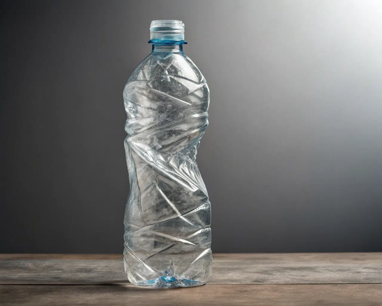
Are you seeing bubbles or incomplete shapes in your bottles?
Your bottles are coming out with defects. The bottom isn't fully formed, the walls have an uneven thickness, or you can see small air bubbles trapped in the plastic.
These are classic signs of air venting problems. The air inside the preform gets trapped during the high-speed blowing process and has nowhere to escape, preventing the plastic from filling the mold cavity completely.
Dive Deeper: The Science of Mold Venting
When you blow a bottle, you are stretching a small, thick-walled preform into a large, thin-walled container. The air that was already inside the preform must be evacuated in milliseconds. If it can't get out of the way fast enough, it fights back against the expanding plastic.
This trapped, high-pressure air can cause a range of common PET blow molding defects.
Where Venting is Most Critical
Venting isn't just one thing; it's a system of tiny channels machined into the mold to let air escape while being too small for the molten plastic to flow through. Key areas include:
- Parting Line: The surface where the two mold halves meet is the largest vent. A tiny, precisely machined gap allows a large volume of air to escape.
- Base/Push-up: The intricate shape of the bottle's base is a common area for air to get trapped. Special vent plugs or textured surfaces are often used here.
- Shoulder and Details: Sharp corners, logos, or ribbed areas can also trap small pockets of air, leading to incomplete details.
Fixing Venting Issues
If you have a mold with venting problems, it can sometimes be fixed, but it's much better to design it correctly from the start.
Design for Venting: Experienced mold designers know where air is likely to get trapped based on the bottle's geometry. They use simulation software to predict air flow and place vents in the most effective locations. A good design brief for your PET bottle mold should always include a review of the proposed venting strategy.
Machining Precision: Vents are often only 0.02mm to 0.04mm deep. This requires high-precision machining. A low-quality mold may have inconsistent or poorly finished vents that either don't work or get clogged easily.
Retrofitting Vents: On an existing mold, a skilled toolmaker can sometimes add or enlarge vents. This can involve re-machining the parting line or drilling holes to insert vent plugs. However, this is a delicate process and isn't always successful.
When you see defects like an undefined base or blurry logos, check your processing parameters first (like preform temperature). But if those are correct, the root cause is very likely insufficient venting in the mold itself. This is a design and manufacturing quality issue that highlights the importance of working with an experienced mold maker.
How can you avoid all these mold failures in the future?
You've seen all the ways a new mold can fail. You are tired of the delays, wasted money, and frustration. How can you make sure this never happens again?
The solution is to be proactive, not reactive. You must provide your supplier with a comprehensive "Mold Design Brief" or checklist before you even place the order.
Dive Deeper: The Ultimate Mold Ordering Checklist
A successful mold project is all about clear communication. You are the expert on your production environment, and the mold maker is the expert on mold design and manufacturing. You must bridge the gap between these two worlds with clear, written data. Don't rely on phone calls or vague emails.
Based on all the issues we've discussed, I've developed a comprehensive checklist. Filling this out and sending it with your RFQ (Request for Quote) will eliminate 99% of potential failures. It forces both you and the supplier to think through every critical detail.
Here is a checklist you can use as a template for your next blow bottle mold order.
Comprehensive Mold Customization & Communication Form
| Section | Parameter | Your Specification |
|---|---|---|
| 1. Machine Information | Blow Molding Machine Brand & Model | e.g., Sidel SBO 14 |
| Mold Mounting Drawing Attached? | Yes / No | |
| Max/Min Mold Thickness (mm) | ||
| 2. Bottle Specification | Target Capacity (ml) & Tolerance (±ml) | e.g., 500ml ± 2ml |
| Target Fill Level Height (mm from top) | e.g., 15mm | |
| Target Overall Height (mm) & Tolerance | e.g., 220mm ± 0.5mm | |
| Target Max Diameter (mm) & Tolerance | e.g., 68mm ± 0.3mm | |
| Bottle Drawing Attached? | Yes / No | |
| 3. Preform Specification | Preform Drawing Attached? | Yes / No |
| Preform Physical Samples Sent? | Yes / No (if no drawing) | |
| Preform Weight (grams) | e.g., 21.5g | |
| Neck Finish Standard | e.g., PCO 1881 | |
| 4. Production Line Info | Capping Machine Type | |
| Labeling Machine Type | ||
| Packing Machine Type | ||
| 5. Mold Features | Number of Cavities | e.g., 4 |
| Mold Material (Core/Cavity/Base) | e.g., Stainless Steel 4CR13 | |
| Cooling Connector Standard Sheet Attached? | Yes / No | |
| 6. Project Requirements | Prototype Mold Required? | Yes / No |
| 3D Bottle/Mold Drawings for Approval? | Yes | |
| Required Delivery Date |
This checklist turns you into an informed customer. It ensures nothing is forgotten. When a supplier receives this level of detail, they know you are a professional, and it sets a high standard for the project from day one. It is the single best tool to ensure your new mold is a productive asset, not a costly failure.
Conclusion
A blow mold failure is rarely a surprise. It's the result of a missed detail in the planning stage. By confirming machine fitment, bottle dimensions, preform specs, and cooling standards upfront, you prevent nearly all common problems.
Frequently Asked Questions (FAQ)
1. What is the single most common reason a new blow mold fails?
The most frequent failure is a physical mounting error. The mold literally does not fit the machine because the mounting plate dimensions, bolt hole pattern, or overall mold thickness were not confirmed with the end-user's specific bottle blowing machine before manufacturing.
2. How much can a PET bottle shrink after molding?
PET bottles can shrink between 1.5% and 2.5% after being ejected from the mold and cooling to room temperature. For a 200mm tall bottle, this could be a change of 3-5mm, which is significant for automated filling and packing lines. The exact rate depends on wall thickness and processing temperatures.
3. Can I fix a mold that was made with the wrong dimensions?
Sometimes, minor fixes are possible but often costly and risky. For example, a mold that is slightly too thick can sometimes be machined down, as in my client's case. Adding material to a mold that is too small is very difficult. Fixing incorrect bottle capacity or dimensions is nearly impossible without remaking the core and cavity, which is essentially making a new mold.
4. What are the top 3 pieces of information I must provide for a custom mold?
- A complete machine mounting drawing: This ensures the mold will fit your machine.
- A detailed preform drawing or physical samples: This guarantees the critical neck-holding mechanism will work correctly.
- A detailed bottle drawing with all dimensions and tolerances: This includes capacity, fill level, height, and diameter, which ensures the final product meets your requirements.
5. Why is the mold cooling connection so important to specify?
If the cooling connectors (type, thread, gender, and position) are not specified, you may not be able to connect your chiller to the mold. Proper cooling is critical for controlling bottle quality and achieving fast, efficient production cycles. A simple connector mismatch can bring your entire production to a halt.
🔗 Learn More about Blow Molding Technology
Blow Molding – Wikipedia
A comprehensive overview of various blow molding processes, including extrusion, injection, and stretch blow molding.Injection Molding – Wikipedia
Important for understanding the production of preforms used in stretch blow molding.Stretch Blow Molding – Wikipedia
Explains how PET bottles are formed through axial and radial stretching processes.PET Bottle – Wikipedia
Background information on the materials and properties of typical PET bottles.Design of PET Bottles – Wikipedia
An introduction to the design considerations and geometry used in PET bottle manufacturing.
🔗 Related Pages on Our Website
Automatic Blow Molding Machines – iBottler
Discover our full range of customizable automatic PET bottle blow molding machines.Blow Bottle Mold – iBottler
Explore our precision blow molds designed for PET and PP bottles.Preform Mold – iBottler
Learn more about our high-precision preform molds suitable for various injection molding machines.PET Wide Mouth Jar Project Starter Guide: Equipment, Molds & Process Explained
How to Choose the Right Preform Neck Size for Your PET Bottle Project
